7. CYLINDER HEAD/VALVES
(Mongoose/KXR 90) Mongoose/KXR 90/50
Bolts
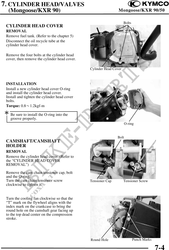
CYLINDER HEAD COVER
REMOVAL
Remove fuel tank. (Refer to the chapter 5)
Disconnect the oil recycle tube at the
cylinder head cover.
Remove the four bolts at the cylinder head
cover, then remove the cylinder head cover.
Cylinder Head Cover
INSTALLATION
Install a new cylinder head cover O-ring
and install the cylinder head cover.
Install and tighten the cylinder head cover
bolts.
Torque: 0.81.2kgf-m
Be sure to install the O-ring into the
groove properly.
O-ring
Bolt
CAMSHAFT/CAMSHAFT
HOLDER
REMOVAL
Remove the cylinder head cover. (Refer to
the "CYLINDER HEAD COVER
REMOVAL")
Remove the cam chain tensioner cap, bolt
and the O-ring.
Turn the cam chain tensioner screw Tensioner Cap Tensioner Screw
clockwise to tighten it.
Turn the cooling fan clockwise so that the
"T" mark on the flywheel aligns with the
index mark on the crankcase to bring the
round hole on the camshaft gear facing up
to the top dead center on the compression
stroke.
Round Hole Punch Marks
7-4