stryker 125 Workshop-manual : Page 229

Microfiches
Image preview

Page 227

Image preview

Page 228

Image preview

Page 230

Image preview

Page 231

1 5 10 15 20 25 30 35 40 45 50 55 60 65 70 75 80 85 90 95 100 105 110 115 120 125 130 135 140 145 150 155 160 165 170 175 180 185 190 195 200 205 210 215 220 225 230 233
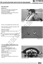
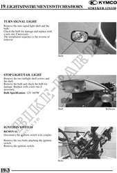
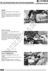
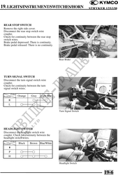
          19. LIGHTS/INSTRUMENT/SWITCHES/HORN                             STRYKER 125/150
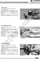


 INSPECTION
 Check for continuity between the wires
 indicated below.
       Color Black       Red   Black/ Green
 Position                      White
   OFF                                 
    ON                    


 STARTER BUTTON
 Remove the decorative covers under the
 fuel tank.
 Disconnect the right switch wire coupler.
 Check for continuity between the black and
 yellow/red wires.
            Color
 Position              Black     Yellow/Red
    FREE
    PUSH                             

                                               Starter Button


 HORN BUTTON
 Remove the decorative covers under the
 fuel tank.
 Disconnect the left switch wire coupler.
 Check for continuity between the black and
 light green wires.
            Color
 Position              Black     Light Green
    FREE
    PUSH                             

                                               Horn Button


                                                                        19-4