Choose your country
We work in partnership with many official Kymco dealers around the world.
You can select the country of your choice from the list below, whatever your choice, we can deliver worldwide!
8. DRIVE AND DRIVEN PULLEYS/
KICK STARTER GRAND DINK 125/150
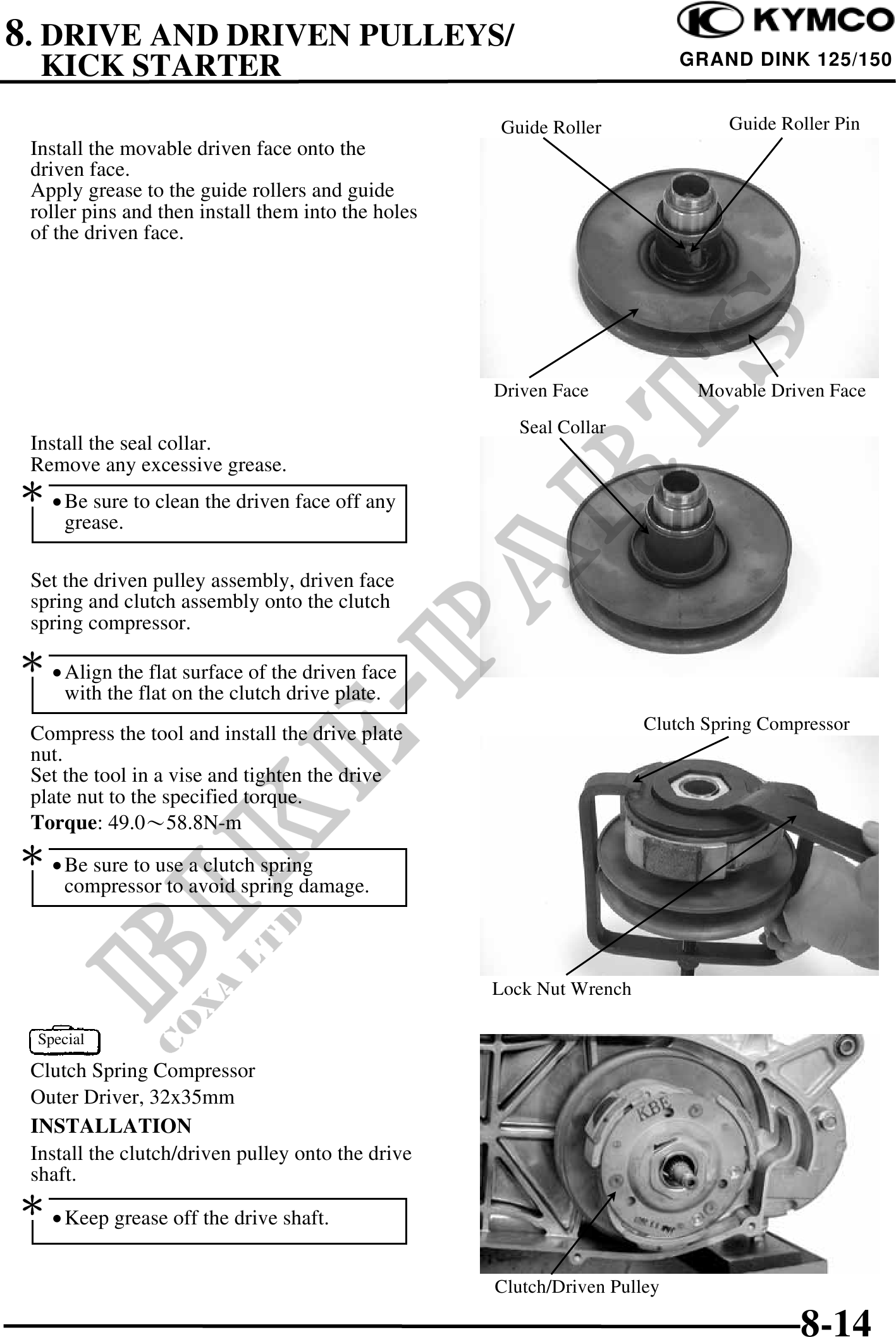
Guide Roller Guide Roller Pin
Install the movable driven face onto the
driven face.
Apply grease to the guide rollers and guide
roller pins and then install them into the holes
of the driven face.
Driven Face Movable Driven Face
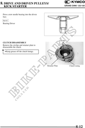
Seal Collar
Install the seal collar.
Remove any excessive grease.
· Be sure to clean the driven face off any
grease.
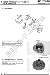
Set the driven pulley assembly, driven face
spring and clutch assembly onto the clutch
spring compressor.
· Align the flat surface of the driven face
with the flat on the clutch drive plate.
Clutch Spring Compressor
Compress the tool and install the drive plate
nut.
Set the tool in a vise and tighten the drive
plate nut to the specified torque.
Torque: 49.058.8N-m
· Be sure to use a clutch spring
compressor to avoid spring damage.
Lock Nut Wrench
Special
Clutch Spring Compressor
Outer Driver, 32x35mm
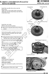
INSTALLATION
Install the clutch/driven pulley onto the drive
shaft.
· Keep grease off the drive shaft.
Clutch/Driven Pulley
8-14