Choose your country
We work in partnership with many official Kymco dealers around the world.
You can select the country of your choice from the list below, whatever your choice, we can deliver worldwide!
19. LIGHTS/SWITCHES MXU 300/250
IGNITION SWITCH
INSPECTION
Disconnect the ignition switch connectors.
(Refer to the "HANDLEBAR COVER
REMOVAL" section in chapter 2.)
Check for continuity between the switch
side connector terminals in each switch
position.
Continuity should exist between the color
coded wires as right:
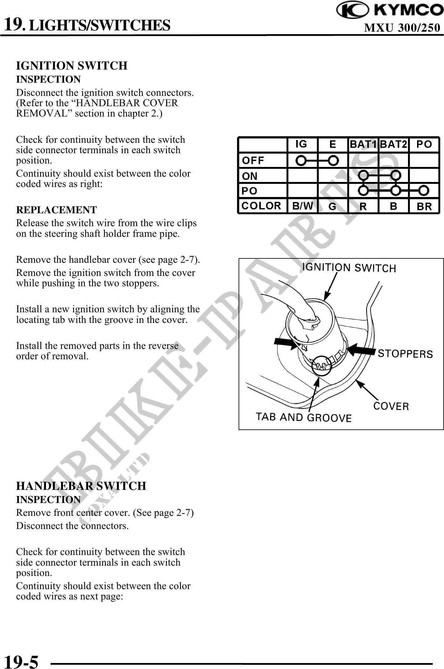
REPLACEMENT
Release the switch wire from the wire clips
on the steering shaft holder frame pipe.
Remove the handlebar cover (see page 2-7).
Remove the ignition switch from the cover
while pushing in the two stoppers.
Install a new ignition switch by aligning the
locating tab with the groove in the cover.
Install the removed parts in the reverse
order of removal.
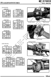
HANDLEBAR SWITCH
INSPECTION
Remove front center cover. (See page 2-7)
Disconnect the connectors.
Check for continuity between the switch
side connector terminals in each switch
position.
Continuity should exist between the color
coded wires as next page:
19-5