Choose your country
We work in partnership with many official Kymco dealers around the world.
You can select the country of your choice from the list below, whatever your choice, we can deliver worldwide!
17. IGNITION SYSTEM People GT 125i
A .C. GENERATOR INSPECTION
CRANK POSITION SENSOR INSPECTION
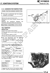
This test is performed with the stator
installed in the engine.
Remove the seat and met-in box.
Disconnect the Crank Position Sensor Wire
Coupler.
Measure the resistance between the
blue/white and green/white wire terminals. Crank Position Sensor Wire Coupler
Blue/YellowGreen/White 11515
TILT SWITCH
INSPECTION
Support the scooter level surface.
Put the side stand up and engine stop switch
is at "RUN".
Turn the ignition switch to "OFF".
Remove the screws, washers and tilt switch.
Do not disconnect the tilt switch
connector during inspection.
The capacity of battery must be fully
charged.
Place the tilt switch vertical as shown at the
ignition switch "ON". Measure the voltage as
below.
Terminal Standard
Violet/Red (+)
Green/Pink (-) 5 V (ECU voltage)
Black/Blue (+) Tilt Switch "UP" Mark
0.41.4 V less
Green/Pink (-)
Incline the tilt switch 6510 degrees to the left
or right at the ignition switch "ON". Measure
the voltage as below.
Terminal Standard
Violet/Red (+)
5 V (ECU voltage)
Green/Pink (-)
Black/Blue (+)
3.74.4 V
Green/Pink (-)
If repeat this test, first turn the ignition switch Connector
to "OFF", then turn the ignition switch to "ON".
17-4