Choose your country
We work in partnership with many official Kymco dealers around the world.
You can select the country of your choice from the list below, whatever your choice, we can deliver worldwide!
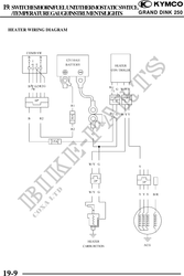
19. SWITCHES/HORN/FUELUNIT/THERMOSTATICSWITCH
/TEMPERATUREGAUGE/INSTRUMENTS/LIGHTS GRAND DINK 250
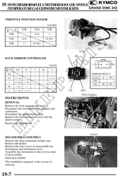
THROTTLE POSTTION SENSOR
Unit:K
V/R V/G V/B
V/R 4~6
V/G 4~6 0~51
V/B 0~51
T.P.S.
V B/L G
BACK MIRROR CONTROLLER
Unit:
W/Y Y/L V B/L G
W/Y
Y/L 5.8~11M 0.2~0.8
V 420~780K 9.3~17M 9.3~17M
B/L 7~13M
G 5.8~11M 0.2~0.8 Y/L W/Y
Wire Couplers
INSTRUMENTS
REMOVAL
Remove the front upper cover. ( 2-5)
Disconnect the instrument wire couplers and
connectors.
Disconnect the speedometer cable.
Remove the four instrument cover and leg
shield screws.
Remove the instruments.
Screws
DISASSEMBLY/ASSEMBLY
Remove the three instrument holder nuts.
Remove the holder.
Remove the four screws to disassemble the
instruments and instrument cover.
Assemble the instruments in the reverse order
of disassembly.
INSTALLATION
The installation sequence is the reverse of
removal.
19-7