Choose your country
We work in partnership with many official Kymco dealers around the world.
You can select the country of your choice from the list below, whatever your choice, we can deliver worldwide!
NOTE: Prior to replacing the CDI unit to assure the
CDI unit is defective, it is advisable to perform a CDI
peak voltage test (see Ignition Coil in this section)
and/or perform a continuity test of the wiring har-
ness from the CDI connector to the CDI unit.
Regulator/Rectifier
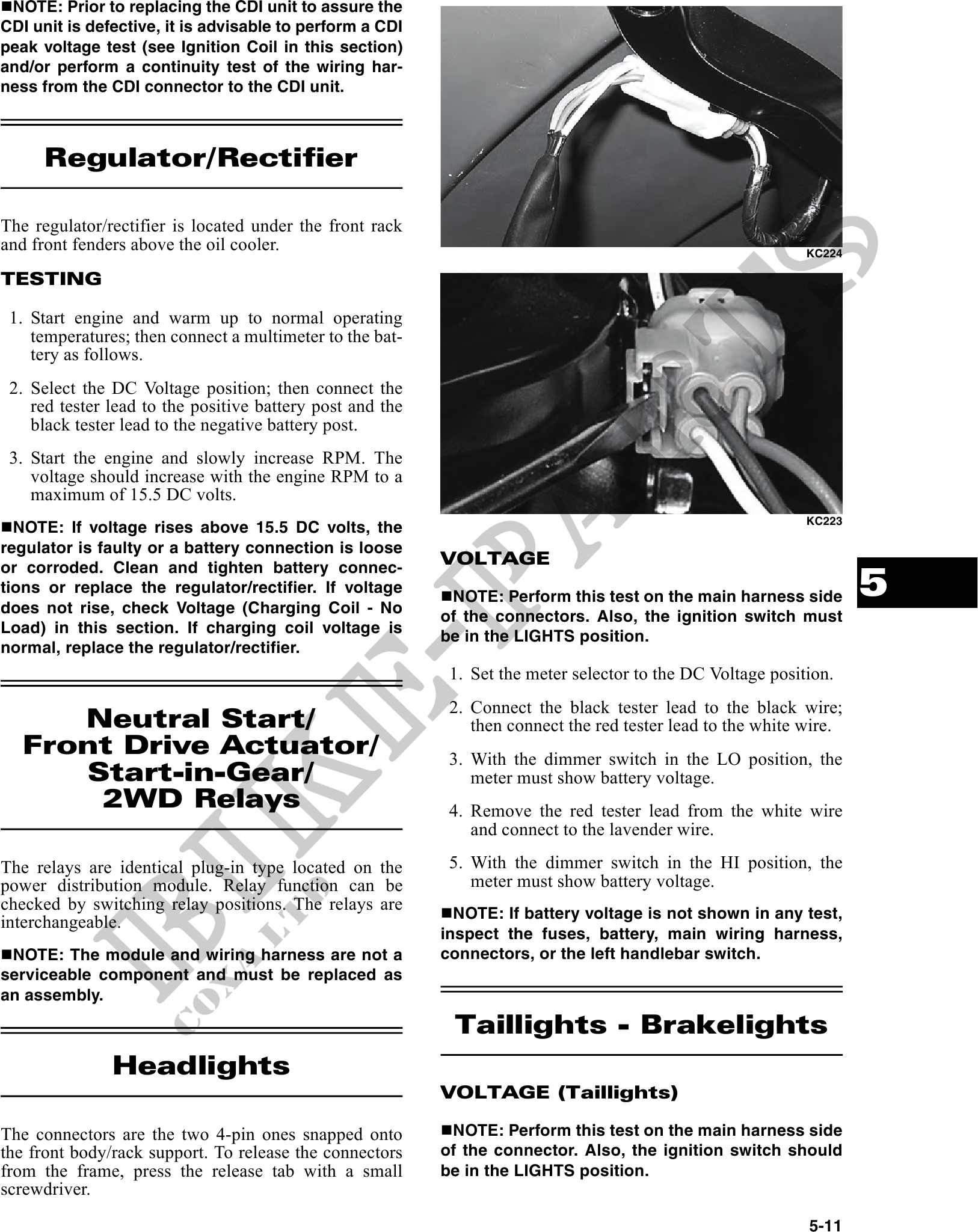
The regulator/rectifier is located under the front rack
and front fenders above the oil cooler. KC224
TESTING
1. Start engine and warm up to normal operating
temperatures; then connect a multimeter to the bat-
tery as follows.
2. Select the DC Voltage position; then connect the
red tester lead to the positive battery post and the
black tester lead to the negative battery post.
3. Start the engine and slowly increase RPM. The
voltage should increase with the engine RPM to a
maximum of 15.5 DC volts.
KC223
NOTE: If voltage rises above 15.5 DC volts, the
regulator is faulty or a battery connection is loose
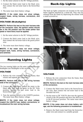
VOLTAGE
5
or corroded. Clean and tighten battery connec-
tions or replace the regulator/rectifier. If voltage
NOTE: Perform this test on the main harness side
does not rise, check Voltage (Charging Coil - No
of the connectors. Also, the ignition switch must
Load) in this section. If charging coil voltage is
be in the LIGHTS position.
normal, replace the regulator/rectifier.
1. Set the meter selector to the DC Voltage position.
2. Connect the black tester lead to the black wire;
Neutral Start/ then connect the red tester lead to the white wire.
Front Drive Actuator/ 3. With the dimmer switch in the LO position, the
Start-in-Gear/ meter must show battery voltage.
2WD Relays 4. Remove the red tester lead from the white wire
and connect to the lavender wire.
The relays are identical plug-in type located on the 5. With the dimmer switch in the HI position, the
power distribution module. Relay function can be meter must show battery voltage.
checked by switching relay positions. The relays are
NOTE: If battery voltage is not shown in any test,
interchangeable.
inspect the fuses, battery, main wiring harness,
NOTE: The module and wiring harness are not a connectors, or the left handlebar switch.
serviceable component and must be replaced as
an assembly.
Taillights - Brakelights
Headlights
VOLTAGE (Taillights)
The connectors are the two 4-pin ones snapped onto NOTE: Perform this test on the main harness side
the front body/rack support. To release the connectors of the connector. Also, the ignition switch should
from the frame, press the release tab with a small be in the LIGHTS position.
screwdriver.
5-11