Choose your country
We work in partnership with many official Kymco dealers around the world.
You can select the country of your choice from the list below, whatever your choice, we can deliver worldwide!
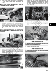
2. Place the valve cover on the Surface Plate covered
with #400 grit wet-or-dry sandpaper. Using light
pressure, move the valve cover in a figure eight
motion. Inspect the sealing surface for any indica-
tion of high spots. A high spot can be noted by a
bright metallic finish. Correct any high spots
before assembly by continuing to move the valve
cover in a figure eight motion until a uniform
bright metallic finish is attained.
! CAUTION
Do not remove an excessive amount of the sealing
surface or damage to the camshaft will result.
MD1211
Always check camshaft clearance when resurfacing
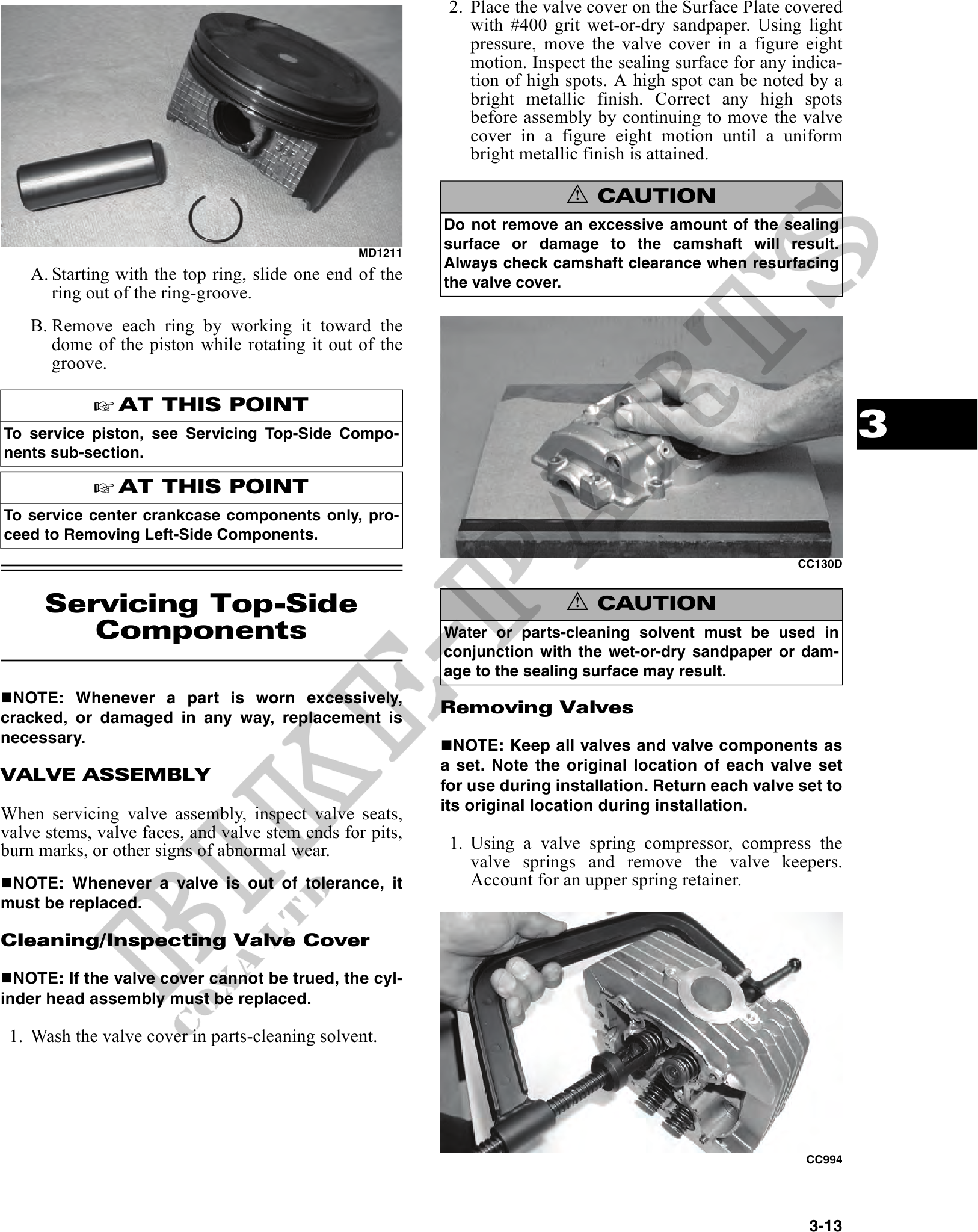
A. Starting with the top ring, slide one end of the the valve cover.
ring out of the ring-groove.
B. Remove each ring by working it toward the
dome of the piston while rotating it out of the
groove.
AT THIS POINT
To service piston, see Servicing Top-Side Compo- 3
nents sub-section.
AT THIS POINT
To service center crankcase components only, pro-
ceed to Removing Left-Side Components.
CC130D
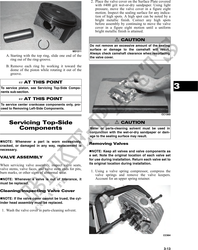
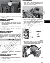
Servicing Top-Side ! CAUTION
Components Water or parts-cleaning solvent must be used in
conjunction with the wet-or-dry sandpaper or dam-
age to the sealing surface may result.
NOTE: Whenever a part is worn excessively,
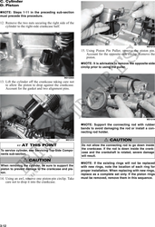
Removing Valves
cracked, or damaged in any way, replacement is
necessary. NOTE: Keep all valves and valve components as
a set. Note the original location of each valve set
VALVE ASSEMBLY
for use during installation. Return each valve set to
its original location during installation.
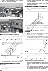
When servicing valve assembly, inspect valve seats,
valve stems, valve faces, and valve stem ends for pits,
burn marks, or other signs of abnormal wear. 1. Using a valve spring compressor, compress the
valve springs and remove the valve keepers.
NOTE: Whenever a valve is out of tolerance, it Account for an upper spring retainer.
must be replaced.
Cleaning/Inspecting Valve Cover
NOTE: If the valve cover cannot be trued, the cyl-
inder head assembly must be replaced.
1. Wash the valve cover in parts-cleaning solvent.
CC994
3-13