My Cart

| Description | Part number | Qty |
|---|
| Description | Part number | Qty |
|---|
ATV-1069 ATV-1085B
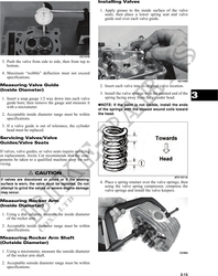
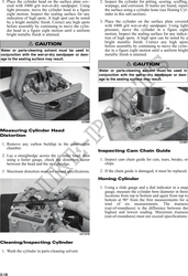
2. Install the compression rings (1 and 2) so the let-
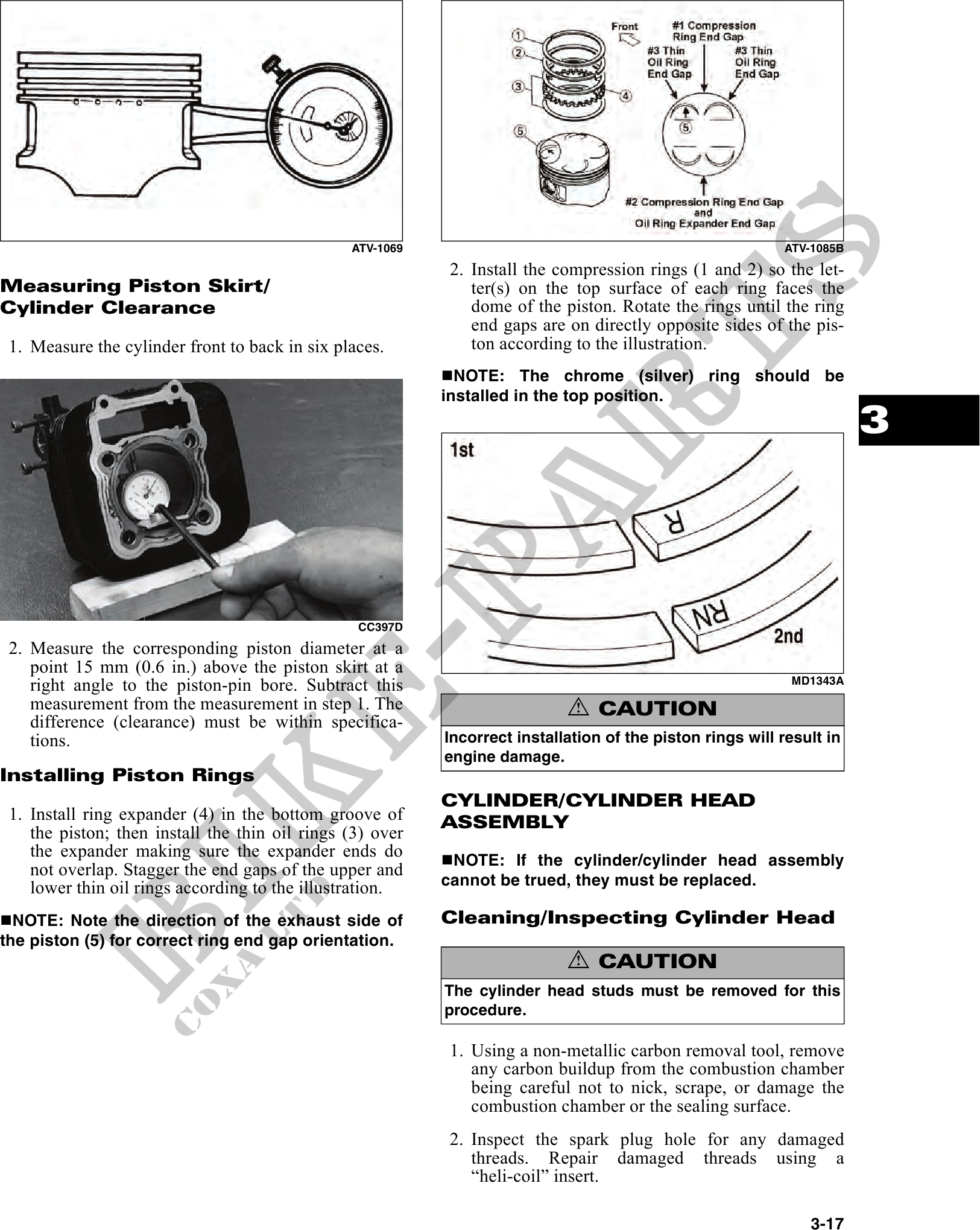
Measuring Piston Skirt/ ter(s) on the top surface of each ring faces the
Cylinder Clearance dome of the piston. Rotate the rings until the ring
end gaps are on directly opposite sides of the pis-
1. Measure the cylinder front to back in six places. ton according to the illustration.
NOTE: The chrome (silver) ring should be
installed in the top position.
3
CC397D
2. Measure the corresponding piston diameter at a
point 15 mm (0.6 in.) above the piston skirt at a
right angle to the piston-pin bore. Subtract this MD1343A
measurement from the measurement in step 1. The ! CAUTION
difference (clearance) must be within specifica-
tions. Incorrect installation of the piston rings will result in
engine damage.
Installing Piston Rings
CYLINDER/CYLINDER HEAD
1. Install ring expander (4) in the bottom groove of ASSEMBLY
the piston; then install the thin oil rings (3) over
the expander making sure the expander ends do NOTE: If the cylinder/cylinder head assembly
not overlap. Stagger the end gaps of the upper and
lower thin oil rings according to the illustration. cannot be trued, they must be replaced.
NOTE: Note the direction of the exhaust side of Cleaning/Inspecting Cylinder Head
the piston (5) for correct ring end gap orientation.
! CAUTION
The cylinder head studs must be removed for this
procedure.
1. Using a non-metallic carbon removal tool, remove
any carbon buildup from the combustion chamber
being careful not to nick, scrape, or damage the
combustion chamber or the sealing surface.
2. Inspect the spark plug hole for any damaged
threads. Repair damaged threads using a
"heli-coil" insert.
3-17