Choose your country
We work in partnership with many official Kymco dealers around the world.
You can select the country of your choice from the list below, whatever your choice, we can deliver worldwide!
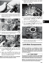
12. With the alignment pin installed in the camshaft
and the cam lobes directed down (toward the pis-
ton), place the camshaft in position and verify that
the timing mark on the magneto is visible through
the inspection plug and that the timing marks on
the camshaft sprocket are parallel with the valve
cover mating surface.
NOTE: When the camshaft assembly is seated,
make sure the alignment pin in the camshaft aligns
with the smallest hole in the sprocket.
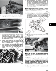
13. With the alignment pin installed in the camshaft,
MD1270 loosely place the cam sprocket (with the recessed
side facing the camshaft lobes) onto the camshaft
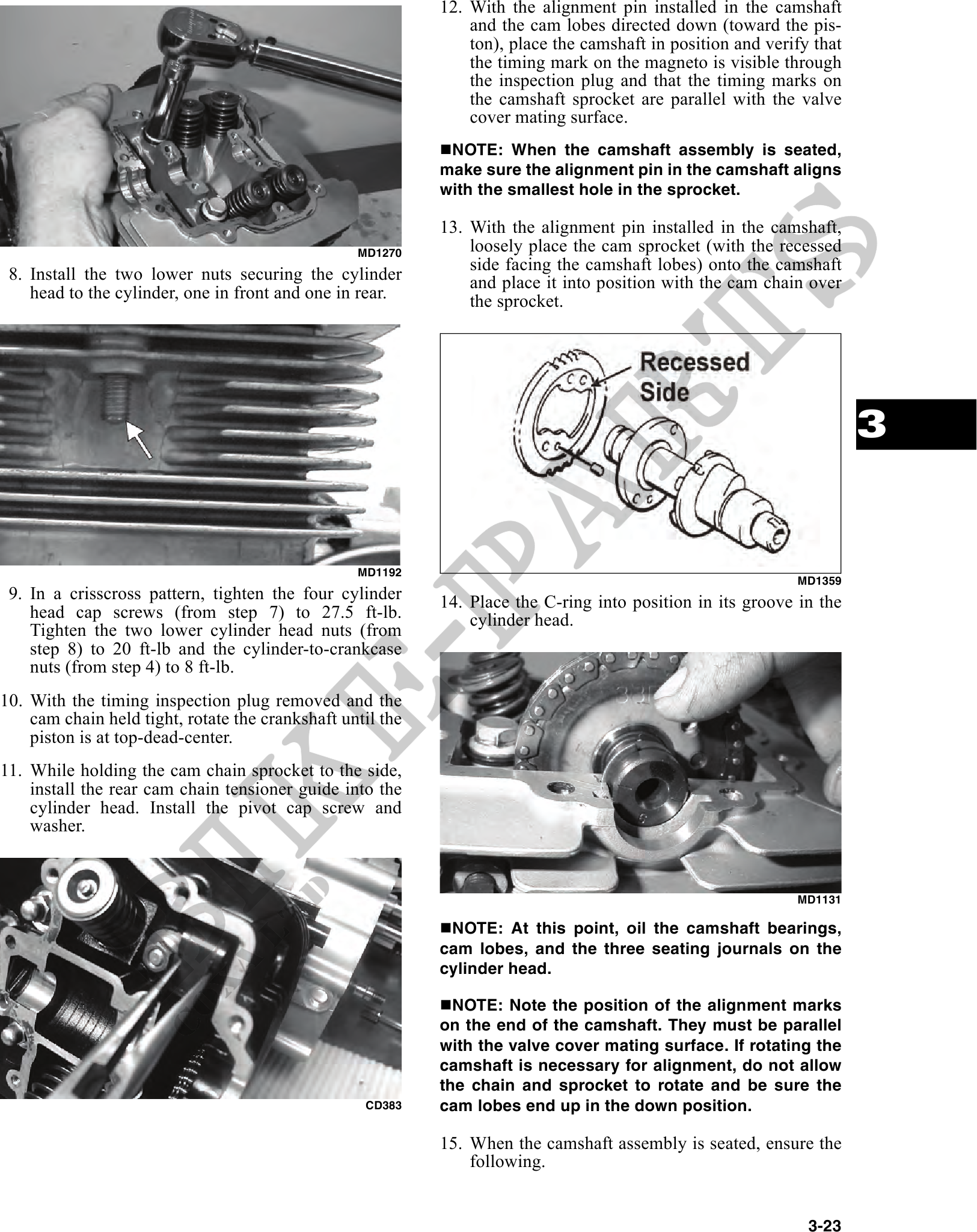
8. Install the two lower nuts securing the cylinder and place it into position with the cam chain over
head to the cylinder, one in front and one in rear. the sprocket.
3
MD1192
MD1359
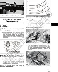
9. In a crisscross pattern, tighten the four cylinder 14. Place the C-ring into position in its groove in the
head cap screws (from step 7) to 27.5 ft-lb. cylinder head.
Tighten the two lower cylinder head nuts (from
step 8) to 20 ft-lb and the cylinder-to-crankcase
nuts (from step 4) to 8 ft-lb.
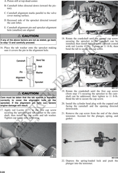
10. With the timing inspection plug removed and the
cam chain held tight, rotate the crankshaft until the
piston is at top-dead-center.
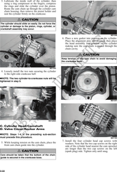
11. While holding the cam chain sprocket to the side,
install the rear cam chain tensioner guide into the
cylinder head. Install the pivot cap screw and
washer.
MD1131
NOTE: At this point, oil the camshaft bearings,
cam lobes, and the three seating journals on the
cylinder head.
NOTE: Note the position of the alignment marks
on the end of the camshaft. They must be parallel
with the valve cover mating surface. If rotating the
camshaft is necessary for alignment, do not allow
the chain and sprocket to rotate and be sure the
CD383 cam lobes end up in the down position.
15. When the camshaft assembly is seated, ensure the
following.
3-23