Choose your country
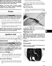
We work in partnership with many official Kymco dealers around the world.
You can select the country of your choice from the list below, whatever your choice, we can deliver worldwide!
4. When the brake pedal is depressed, the meter must
show less than 1 ohm.
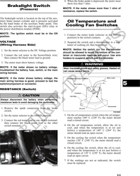
Brakelight Switch
(Pressure) NOTE: If the meter shows more than 1 ohm of
resistance, replace the switch.
The brakelight switch is located on the top of the aux-
iliary brake master cylinder and is pressure activated Oil Temperature and
by the hand brake or the auxiliary brake pedal. This
switch also activates the start-in-gear (SIG) relay in Cooling Fan Switches
the power distribution module (PDM).
NOTE: The ignition switch must be in the ON
1. Connect the meter leads (selector in the OHMS
position. position) to the switch contacts.
VOLTAGE 2. Suspend the switch and a thermometer in a con-
(Wiring Harness Side) tainer of cooking oil; then heat the oil.
1. Set the meter selector to the DC Voltage position. NOTE: Neither the switch nor the thermometer
should be allowed to touch the bottom of the con-
2. Connect the red tester to the brown/black wire; tainer or inaccurate readings will occur. Use wire
then connect the black tester lead to ground. holders to suspend switch and thermometer.
3. The meter must show battery voltage.
! WARNING
NOTE: If the meter shows no battery voltage, Wear insulated gloves and safety glasses. Heated oil
troubleshoot the battery, fuse, switch, or the main can cause severe burns.
wiring harness.
NOTE: If the meter shows battery voltage, the
5
main wiring harness is good; proceed to test the
switch/component or connector.
RESISTANCE (Switch)
! CAUTION
Always disconnect the battery when performing
resistance tests to avoid damaging the multimeter.
1. Remove the spade connectors from the brake
switch. 733-554C
2. Set the meter selector to the OHMS position. 3. On the oil temperature switch when the oil temper-
ature reaches 160° C (320° F), the meter should
3. Connect the red tester lead to one switch terminal; read a closed circuit.
then connect the black tester lead to the other
switch terminal. 4. On the oil temperature switch, allow the oil to
cool, and when the temperature is at (or just
before) a temperature of 140° C (284° F), the
meter should read an open circuit.
5. On the cooling fan switch when the temperature
reaches 120° C (248° F), the meter should read a
closed circuit.
6. On the cooling fan switch, allow the oil to cool,
and when the temperature is at (or just before) a
temperature of 110° C (230° F), the meter should
read an open circuit.
7. If the readings are not as indicated, the switch
must be replaced.
KC274
5-3