Choose your country
We work in partnership with many official Kymco dealers around the world.
You can select the country of your choice from the list below, whatever your choice, we can deliver worldwide!
6. CYLINDER HEAD/VALVES GRAND DINK 125/150
SERVICE INFORMATION
GENERAL INSTRUCTIONS
· The cylinder head can be serviced with the engine installed in the frame. Coolant in the radiator
and water jacket must be drained first.
· When assembling, apply molybdenum disulfide grease or engine oil to the valve guide movable
parts and valve arm sliding surfaces for initial lubrication.
· The valve rocker arms are lubricated by engine oil through the cylinder head engine oil passages.
Clean and unclog the oil passages before assembling the cylinder head.
· After disassembly, clean the removed parts and dry them with compressed air before inspection.
· After removal, mark and arrange the removed parts in order. When assembling, install them in
the reverse order of removal.
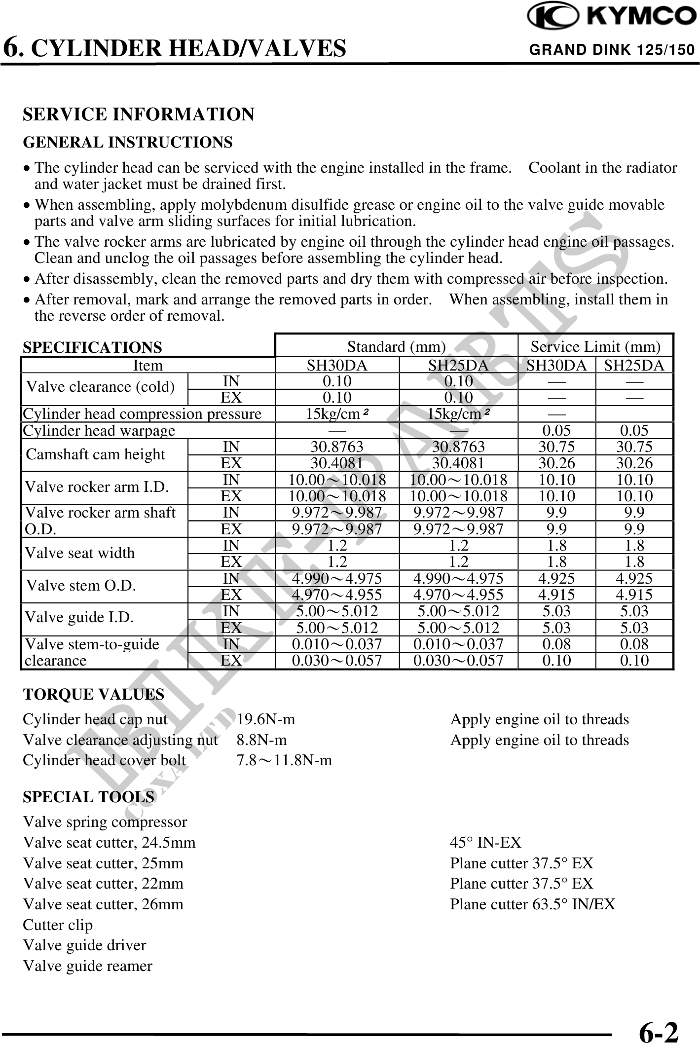
SPECIFICATIONS Standard (mm) Service Limit (mm)
Item SH30DA SH25DA SH30DA SH25DA
Valve clearance (cold) IN 0.10 0.10
EX 0.10 0.10
Cylinder head compression pressure 15kg/cm 15kg/cm
Cylinder head warpage 0.05 0.05
Camshaft cam height IN 30.8763 30.8763 30.75 30.75
EX 30.4081 30.4081 30.26 30.26
Valve rocker arm I.D. IN 10.0010.018 10.0010.018 10.10 10.10
EX 10.0010.018 10.0010.018 10.10 10.10
Valve rocker arm shaft IN 9.9729.987 9.9729.987 9.9 9.9
O.D. EX 9.9729.987 9.9729.987 9.9 9.9
Valve seat width IN 1.2 1.2 1.8 1.8
EX 1.2 1.2 1.8 1.8
Valve stem O.D. IN 4.9904.975 4.9904.975 4.925 4.925
EX 4.9704.955 4.9704.955 4.915 4.915
Valve guide I.D. IN 5.005.012 5.005.012 5.03 5.03
EX 5.005.012 5.005.012 5.03 5.03
Valve stem-to-guide IN 0.0100.037 0.0100.037 0.08 0.08
clearance EX 0.0300.057 0.0300.057 0.10 0.10
TORQUE VALUES
Cylinder head cap nut 19.6N-m Apply engine oil to threads
Valve clearance adjusting nut 8.8N-m Apply engine oil to threads
Cylinder head cover bolt 7.811.8N-m
SPECIAL TOOLS
Valve spring compressor
Valve seat cutter, 24.5mm 45° IN-EX
Valve seat cutter, 25mm Plane cutter 37.5° EX
Valve seat cutter, 22mm Plane cutter 37.5° EX
Valve seat cutter, 26mm Plane cutter 63.5° IN/EX
Cutter clip
Valve guide driver
Valve guide reamer
6-2