Choose your country
We work in partnership with many official Kymco dealers around the world.
You can select the country of your choice from the list below, whatever your choice, we can deliver worldwide!

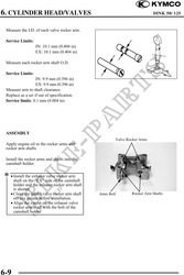
6. CYLINDER HEAD/VALVES DINK 50/ 125
CAMSHAFT HOLDER
REMOVAL
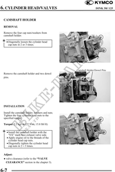
Remove the four cap nuts/washers from
camshaft holder.
· Diagonally loosen the cylinder head
cap nuts in 2 or 3 times.
Camshaft Holder/Dowel Pins
Remove the camshaft holder and two dowel
pins.
INSTALLATION
Install the camshaft holder, washers and nuts.
Tighten the four cylinder head nuts to the
specified torque.
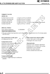
Torque: 2.2 kgf-m (22 N-m, 15.8 lbf-ft)
· Install the camshaft holder with the
"EX" mark face exhaust valve side.
· Apply engine oil to the threads of the
cylinder head cap nuts.
· Diagonally tighten the cylinder head
cap nuts in 23 times.
Adjust:
valve clearance (refer to the "VALVE
CLEARANCE" section in the chapter 3).
6-7