Choose your country
We work in partnership with many official Kymco dealers around the world.
You can select the country of your choice from the list below, whatever your choice, we can deliver worldwide!
19. SWITCHES/HORN/FUELUNIT/THERMOSTATICSWITCH
/TEMPERATUREGAUGE/INSTRUMENTS/LIGHTS GRAND DINK 250
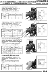
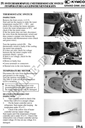
HORN BUTTON INSPECTION
Remove the frame front covers. ( 2-5)
Disconnect the horn wire couplers.
Depress the horn button and check for
continuity between the wire terminals.
Color Light Green Brown/Blue
Position
FREE
PUSH
Horn Button
TURN SIGNAL SWITCH INSPECTION
Remove the frame front covers. ( 2-5)
Disconnect the turn signal switch wire
couplers and turn on the turn signal switch.
Check for continuity between the wire
terminals.
Color Light Blue/ Gray Orange/
Position White White
L
N
R Turn Signal Switch
DIMMER SWITCH INSPECTION Dimmer Switch
Remove the frame front covers. ( 2-5)
Disconnect the headlight dimmer switch wire
couplers.
Turn on the dimmer switch and check for
continuity between the wire terminals.
Color White/
Blue White Brown/
Position Blue Blue
LO
HI
PASSING PASSING
STOP SWITCH INSPECTION
Remove the frame front covers. ( 2-5)
Disconnect the front/rear stop switch wire
couplers.
Check for continuity between the wire
terminals when the front brake lever is
applied.
Color Brown/Blue Green/Yellow
Position
FREE
APPLY Stop Switch
19-4