people 250 s Workshop-manual : Page 215

Microfiches
Image preview

Page 213

Image preview

Page 214

Image preview

Page 216

Image preview

Page 217

1 5 10 15 20 25 30 35 40 45 50 55 60 65 70 75 80 85 90 95 100 105 110 115 120 125 130 135 140 145 150 155 160 165 170 175 180 185 190 195 200 205 210 215 220 225 230 235 240 243
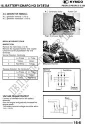
          16. BATTERY/CHARGING SYSTEM                                                PEOPLE/PEOPLE S 250


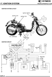
                                                   A.C. Generator Stator         Pulser Coil
 A.C. GENERATOR REMOVAL
 A.C. generator removal ( 10-3)
 A.C. generator installation ( 10-6)


                                                   Right Crankcase Cover             Bolts

 REGULATOR/RECTIFIER
 INSPECTION
 Remove the met-in box. ( 2-6)
 Remove the regulator/rectifier wire coupler.
 Check the continuity between the wire
 terminals.
 Normal Direction: Continuity
                  (+) Probe      (-) Probe
        I          Yellow           Green
       II        Red/White          Yellow       Regulator/Rectifier

 Reverse Direction: No Continuity                 Normal                    Red/White
                  (+) Probe      (-) Probe        Direction
        I           Green           Yellow
                                                          Yellow


       II          Yellow        Red/White


                                                                                       Reverse
                                                                   Green               Direction


 VOLTAGE REGULATION TEST
 Connect a voltmeter across the battery                                       Black
 terminals.
 Start the engine and gradually increase the
 engine speed.
 The battery terminal voltage should be within
 14.015.0V.


                                                                    Voltage Sensor


                                                                                             16-6