Choose your country
We work in partnership with many official Kymco dealers around the world.
You can select the country of your choice from the list below, whatever your choice, we can deliver worldwide!
16. STARTING SYSTEM SUPER8 125
Spring Roller
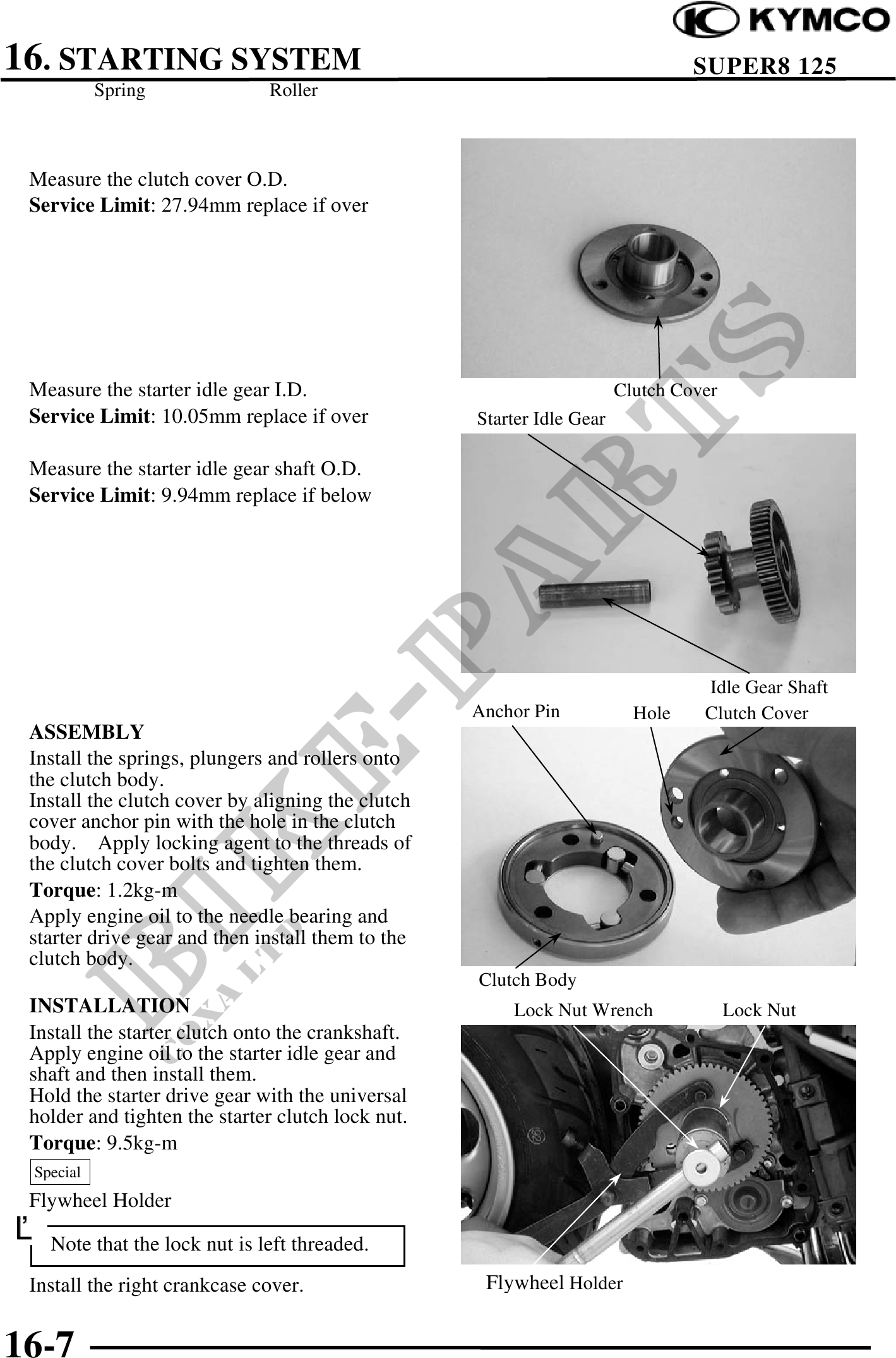
Measure the clutch cover O.D.
Service Limit: 27.94mm replace if over
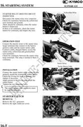
Measure the starter idle gear I.D. Clutch Cover
Service Limit: 10.05mm replace if over Starter Idle Gear
Measure the starter idle gear shaft O.D.
Service Limit: 9.94mm replace if below
Idle Gear Shaft
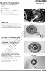
Anchor Pin Hole Clutch Cover
ASSEMBLY
Install the springs, plungers and rollers onto
the clutch body.
Install the clutch cover by aligning the clutch
cover anchor pin with the hole in the clutch
body. Apply locking agent to the threads of
the clutch cover bolts and tighten them.
Torque: 1.2kg-m
Apply engine oil to the needle bearing and
starter drive gear and then install them to the
clutch body.
Clutch Body
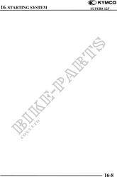
INSTALLATION Lock Nut Wrench Lock Nut
Install the starter clutch onto the crankshaft.
Apply engine oil to the starter idle gear and
shaft and then install them.
Hold the starter drive gear with the universal
holder and tighten the starter clutch lock nut.
Torque: 9.5kg-m
Special
Flywheel Holder
Note that the lock nut is left threaded.
Install the right crankcase cover. Flywheel Holder
16-7