Choose your country
We work in partnership with many official Kymco dealers around the world.
You can select the country of your choice from the list below, whatever your choice, we can deliver worldwide!
16. STARTING SYSTEM AGILITY 50
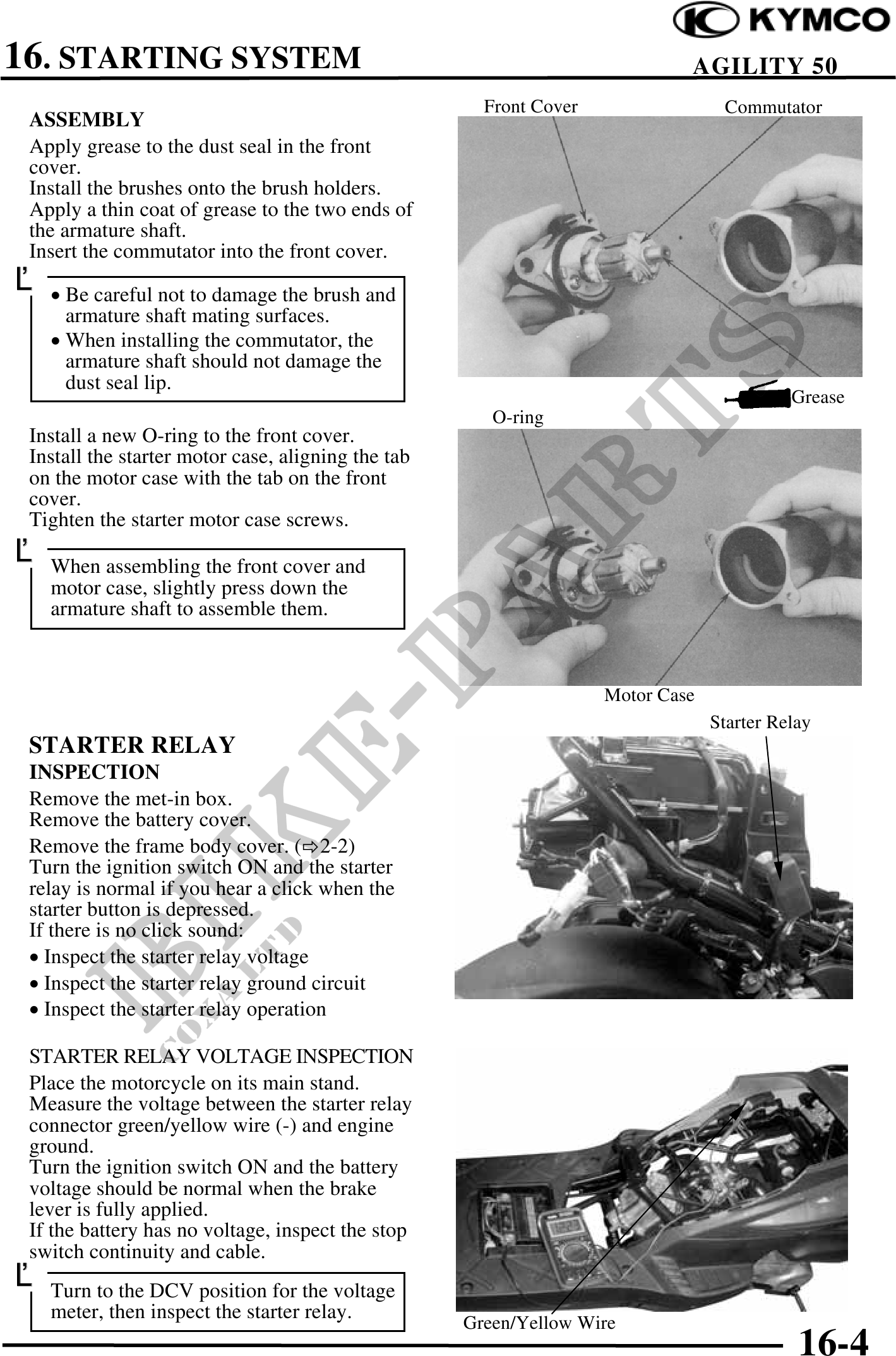
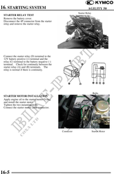
Front Cover Commutator
ASSEMBLY
Apply grease to the dust seal in the front
cover.
Install the brushes onto the brush holders.
Apply a thin coat of grease to the two ends of
the armature shaft.
Insert the commutator into the front cover.
· Be careful not to damage the brush and
armature shaft mating surfaces.
· When installing the commutator, the
armature shaft should not damage the
dust seal lip.
Grease
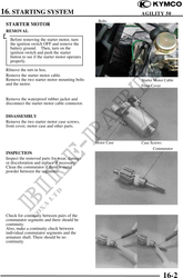
O-ring
Install a new O-ring to the front cover.
Install the starter motor case, aligning the tab
on the motor case with the tab on the front
cover.
Tighten the starter motor case screws.
When assembling the front cover and
motor case, slightly press down the
armature shaft to assemble them.
Motor Case
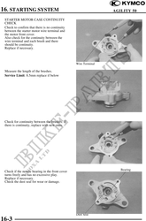
Starter Relay
STARTER RELAY
INSPECTION
Remove the met-in box.
Remove the battery cover.
Remove the frame body cover. ( 2-2)
Turn the ignition switch ON and the starter
relay is normal if you hear a click when the
starter button is depressed.
If there is no click sound:
· Inspect the starter relay voltage
· Inspect the starter relay ground circuit
· Inspect the starter relay operation
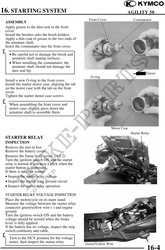
STARTER RELAY VOLTAGE INSPECTION
Place the motorcycle on its main stand.
Measure the voltage between the starter relay
connector green/yellow wire (-) and engine
ground.
Turn the ignition switch ON and the battery
voltage should be normal when the brake
lever is fully applied.
If the battery has no voltage, inspect the stop
switch continuity and cable.
Turn to the DCV position for the voltage
meter, then inspect the starter relay. Green/Yellow Wire
16-4