Choose your country
We work in partnership with many official Kymco dealers around the world.
You can select the country of your choice from the list below, whatever your choice, we can deliver worldwide!
7. CYLINDER HEAD/VALVES AGILITY CITY 125
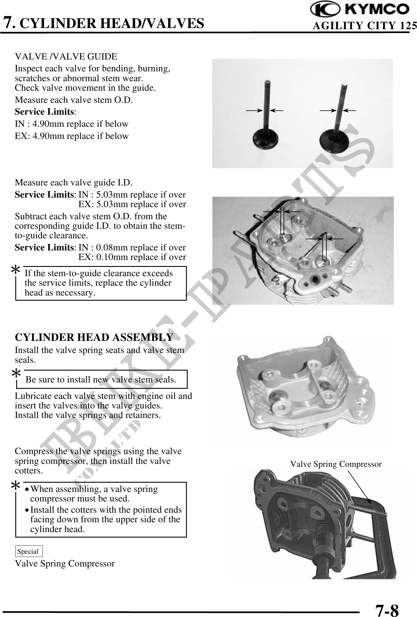
VALVE /VALVE GUIDE
Inspect each valve for bending, burning,
scratches or abnormal stem wear.
Check valve movement in the guide.
Measure each valve stem O.D.
Service Limits:
IN : 4.90mm replace if below
EX: 4.90mm replace if below
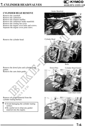
Measure each valve guide I.D.
Service Limits: IN : 5.03mm replace if over
EX: 5.03mm replace if over
Subtract each valve stem O.D. from the
corresponding guide I.D. to obtain the stem-
to-guide clearance.
Service Limits: IN : 0.08mm replace if over
EX: 0.10mm replace if over
If the stem-to-guide clearance exceeds
the service limits, replace the cylinder
head as necessary.
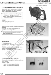
CYLINDER HEAD ASSEMBLY
Install the valve spring seats and valve stem
seals.
Be sure to install new valve stem seals.
Lubricate each valve stem with engine oil and
insert the valves into the valve guides.
Install the valve springs and retainers.
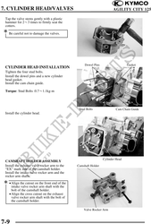
Compress the valve springs using the valve
spring compressor, then install the valve Valve Spring Compressor
cotters.
· When assembling, a valve spring
compressor must be used.
· Install the cotters with the pointed ends
facing down from the upper side of the
cylinder head.
Special
Valve Spring Compressor
7-8