Choose your country
We work in partnership with many official Kymco dealers around the world.
You can select the country of your choice from the list below, whatever your choice, we can deliver worldwide!
3. Using a feeler gauge, check each valve/tappet
clearance. If clearance is not within specifications,
loosen the jam nut and rotate the tappet adjuster
screw until the clearance is within specifications.
Tighten each jam nut securely after completing the
adjustment.
! CAUTION
The feeler gauge must be positioned at the same
angle as the valve and valve adjuster for an accurate
measurement of clearance. Failure to measure the
valve clearance accurately could cause valve com-
KC123 ponent damage.
VALVE/TAPPET CLEARANCE
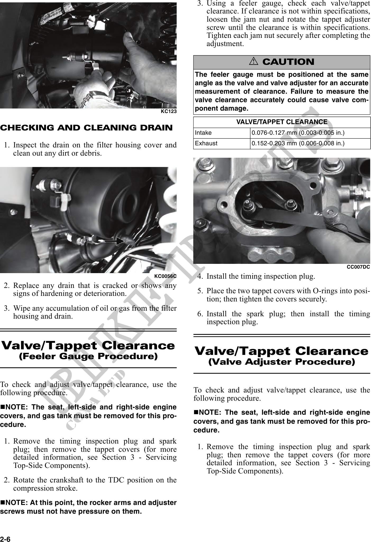
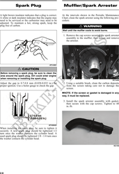
CHECKING AND CLEANING DRAIN
Intake 0.076-0.127 mm (0.003-0.005 in.)
1. Inspect the drain on the filter housing cover and Exhaust 0.152-0.203 mm (0.006-0.008 in.)
clean out any dirt or debris.
CC007DC
KC0056C 4. Install the timing inspection plug.
2. Replace any drain that is cracked or shows any
signs of hardening or deterioration. 5. Place the two tappet covers with O-rings into posi-
tion; then tighten the covers securely.
3. Wipe any accumulation of oil or gas from the filter
housing and drain. 6. Install the spark plug; then install the timing
inspection plug.
Valve/Tappet Clearance Valve/Tappet Clearance
(Feeler Gauge Procedure)
(Valve Adjuster Procedure)
To check and adjust valve/tappet clearance, use the
following procedure. To check and adjust valve/tappet clearance, use the
following procedure.
NOTE: The seat, left-side and right-side engine
covers, and gas tank must be removed for this pro- NOTE: The seat, left-side and right-side engine
cedure. covers, and gas tank must be removed for this pro-
cedure.
1. Remove the timing inspection plug and spark
plug; then remove the tappet covers (for more 1. Remove the timing inspection plug and spark
detailed information, see Section 3 - Servicing plug; then remove the tappet covers (for more
Top-Side Components). detailed information, see Section 3 - Servicing
Top-Side Components).
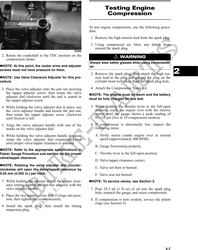
2. Rotate the crankshaft to the TDC position on the
compression stroke.
NOTE: At this point, the rocker arms and adjuster
screws must not have pressure on them.
2-6