Choose your country
We work in partnership with many official Kymco dealers around the world.
You can select the country of your choice from the list below, whatever your choice, we can deliver worldwide!
16. STARTING SYSTEM AGILITY CITY 125
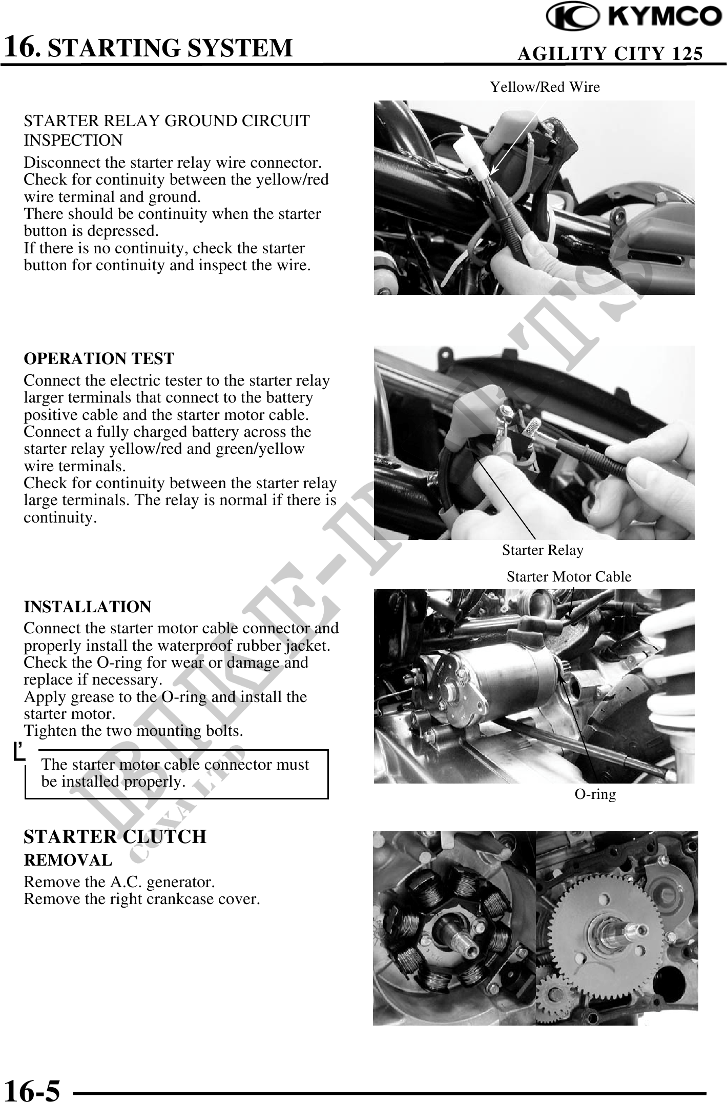
Yellow/Red Wire
STARTER RELAY GROUND CIRCUIT
INSPECTION
Disconnect the starter relay wire connector.
Check for continuity between the yellow/red
wire terminal and ground.
There should be continuity when the starter
button is depressed.
If there is no continuity, check the starter
button for continuity and inspect the wire.
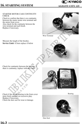
OPERATION TEST
Connect the electric tester to the starter relay
larger terminals that connect to the battery
positive cable and the starter motor cable.
Connect a fully charged battery across the
starter relay yellow/red and green/yellow
wire terminals.
Check for continuity between the starter relay
large terminals. The relay is normal if there is
continuity.
Starter Relay
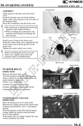
Starter Motor Cable
INSTALLATION
Connect the starter motor cable connector and
properly install the waterproof rubber jacket.
Check the O-ring for wear or damage and
replace if necessary.
Apply grease to the O-ring and install the
starter motor.
Tighten the two mounting bolts.
The starter motor cable connector must
be installed properly.
O-ring
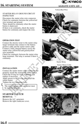
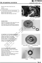
STARTER CLUTCH
REMOVAL
Remove the A.C. generator.
Remove the right crankcase cover.
16-5