grand dink 250 Workshop-manual : Page 67

Microfiches
Image preview

Page 65

Image preview

Page 66

Image preview

Page 68

Image preview

Page 69

1 5 10 15 20 25 30 35 40 45 50 55 60 65 70 75 80 85 90 95 100 105 110 115 120 125 130 135 140 145 150 155 160 165 170 175 180 185 190 195 200 205 210 215 220
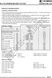
          6. CYLINDER HEAD/VALVES                                               GRAND DINK 250
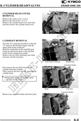
                                                        Cylinder Head Cover
 CYLINDER HEAD COVER
 REMOVAL
 Remove the center cover. ( 2-3)
 Remove the met-in box. ( 2-3)
 Remove the cylinder head cover four bolts
 and then remove the cylinder head cover.


                                                                      Bolt


 CAMSHAFT REMOVAL
 Turn the A.C. generator flywheel so that the
 "T" mark on the flywheel aligns with the
 index mark on the crankcase.
 Hold the round hole on the camshaft gear
 facing up and the location is the top dead
 center on the compression stroke.
 Remove the two bolts attaching cam chain
 tensioner and the tensioner.

                                                Cam Chain Tensioner             Round Hole
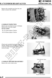
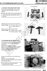
                                                                              Camshaft Holder
 First remove the two bolts between the
 cylinder head and cylinder.
 Then, remove the four cap nuts attaching the
 cylinder head.
 · Diagonally loosen the cylinder head
     cap nuts in 2 or 3 times.


                                                Bolts                           Cap Nuts
                                                                       Camshaft Holder
 Remove the camshaft holder and dowel pins.


                                                                                           6-4