My Cart

| Description | Part number | Qty |
|---|
| Description | Part number | Qty |
|---|
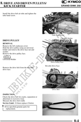
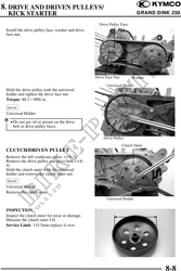
8. DRIVE AND DRIVEN PULLEYS/
KICK STARTER GRAND DINK 250
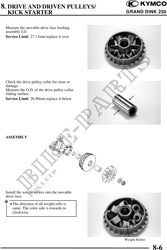
Measure the movable drive face bushing
assembly I.D.
Service Limit: 27.13mm replace if over
Check the drive pulley collar for wear or
damage.
Measure the O.D. of the drive pulley collar
sliding surface.
Service Limit: 26.90mm replace if below
ASSEMBLY
Install the weight rollers into the movable
drive face.
· The direction of all weight rolls is
same. The color side is towards to
clockwise.
Weight Roller
8-6