18. STARTING SYSTEM GRAND DINK 250
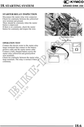
STARTER RELAY INSPECTION
Disconnect the starter relay wire connector.
Check for continuity between the yellow/red
wire terminal and ground.
There should be continuity when the starter
button is depressed.
If there is no continuity, check the starter
button for continuity and inspect the wire.
Yellow/Red Wire
Starter Relay
OPERATION TEST
Connect the electric tester to the starter relay
larger terminals that connect to the battery
positive cable and the starter motor cable.
Connect a fully charged battery across the
starter relay yellow/red and green/yellow
wire terminals.
Check for continuity between the starter relay
large terminals. The relay is normal if there is
continuity.
18-6