3. INSPECTION/ADJUSTMENT GRAND DINK 250
Bolts
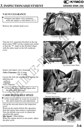
VALVE CLEARANCE
· Inspect and adjust valve clearance
while the engine is cold (below 35).
Remove the cylinder head cover.
Cylinder Head Cover
Turn the A.C. generator flywheel to the top
dead center (TDC) on the compression stroke
so that the "T" mark on the flywheel aligns
with the index mark on the left crankcase
cover.
Top Dead Center Mark
Inspect and adjust valve clearance.
Valve Clearance: IN: 0.1mm
EX: 0.1mm
Loosen the lock nut and adjust by turning the
adjusting nut
Special
Valve Adjuster
· Check the valve clearance again after
the lock nut is tightened.
Feeler Gauge
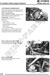
CARBURETOR IDLE SPEED
Throttle Stop Screw
· The engine must be warm for accurate
idle speed inspection and adjustment.
Lift up the seat and remove the inspection
cover.
Warm up the engine before this operation.
Start the engine and connect a tachometer.
Turn the throttle stop screw to obtain the
specified idle speed.
Idle Speed: 1700100rpm
When the engine misses or run erratic, adjust
the pilot screw.
Pilot Screw
3-6