12. FRONT WHEEL/FRONT BRAKE/FRONT
SUSPENSION/STEERING SYSTEM ATV 150/125
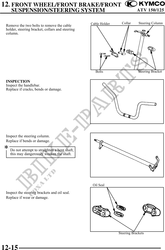
Inspect the tie-rod.
Replace if bend or damage.
Check the tie-rod end movement.
Replace if the tie-rod end exists free play or
turns roughly.
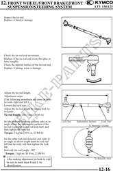
Check the tapered surface of the tie-rod end.
Replace if pitting, wear or damage.
Adjust the tie-rod length.
Adjustment steps:
(The following procedures are done on both
tie-rods, right and left.)
Loosen the lock nuts.
Adjust the tie-rod length by tuning both tie-
rod ends.
Tie rod length: 266.5 mm (10.66 in)
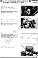
Set the rod-end (steering column side) in an Lock Nut Indentation Surface Lock Nut
angle where the indentation surface of the
tie-rod is parallel to the rod-end shaft, and To Steering Column
then tighten the lock nut.
Torque: 3 kgf-m (30 N-m, 22 lbf-ft)
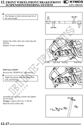
Set the other rod-end (knuckle arm side) in
an angle as shown (right-hand tie-rod and
left-had tie-rod), and then tighten the lock
nut.
Rod-end (tie rod) angle: 180
Torque: 3 kgf-m (30 N-m, 22 lbf-ft)
To Knuckle Arm
After making adjustment on both tie rods
be sure to mark them R and L for
identification.
12-16