Choose your country
We work in partnership with many official Kymco dealers around the world.
You can select the country of your choice from the list below, whatever your choice, we can deliver worldwide!
16. BATTERY/CHARGING SYSTEM GRAND DINK 250
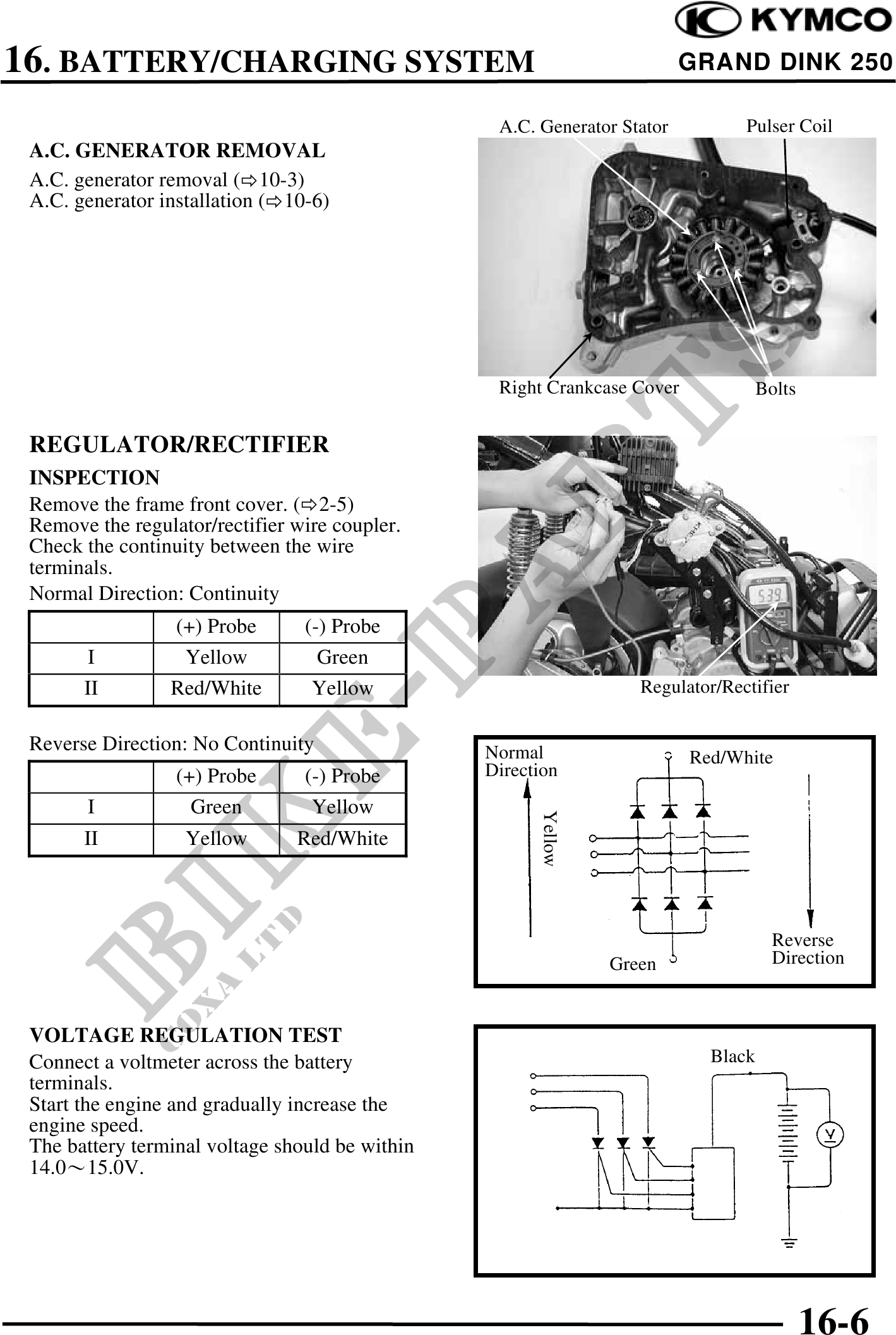
A.C. Generator Stator Pulser Coil
A.C. GENERATOR REMOVAL
A.C. generator removal ( 10-3)
A.C. generator installation ( 10-6)
Right Crankcase Cover Bolts
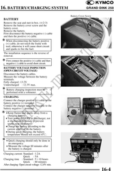
REGULATOR/RECTIFIER
INSPECTION
Remove the frame front cover. ( 2-5)
Remove the regulator/rectifier wire coupler.
Check the continuity between the wire
terminals.
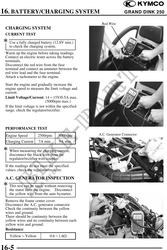
Normal Direction: Continuity
(+) Probe (-) Probe
I Yellow Green
II Red/White Yellow Regulator/Rectifier
Reverse Direction: No Continuity Normal Red/White
(+) Probe (-) Probe Direction
I Green Yellow
Yellow
II Yellow Red/White
Reverse
Green Direction
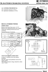
VOLTAGE REGULATION TEST
Connect a voltmeter across the battery Black
terminals.
Start the engine and gradually increase the
engine speed.
The battery terminal voltage should be within
14.015.0V.
Voltage Sensor
16-6