17. IGNITION SYSTEM GRAND DINK 250
A .C. GENERATOR INSPECTION
EXCITER COIL/PULSER COIL
INSPECTION
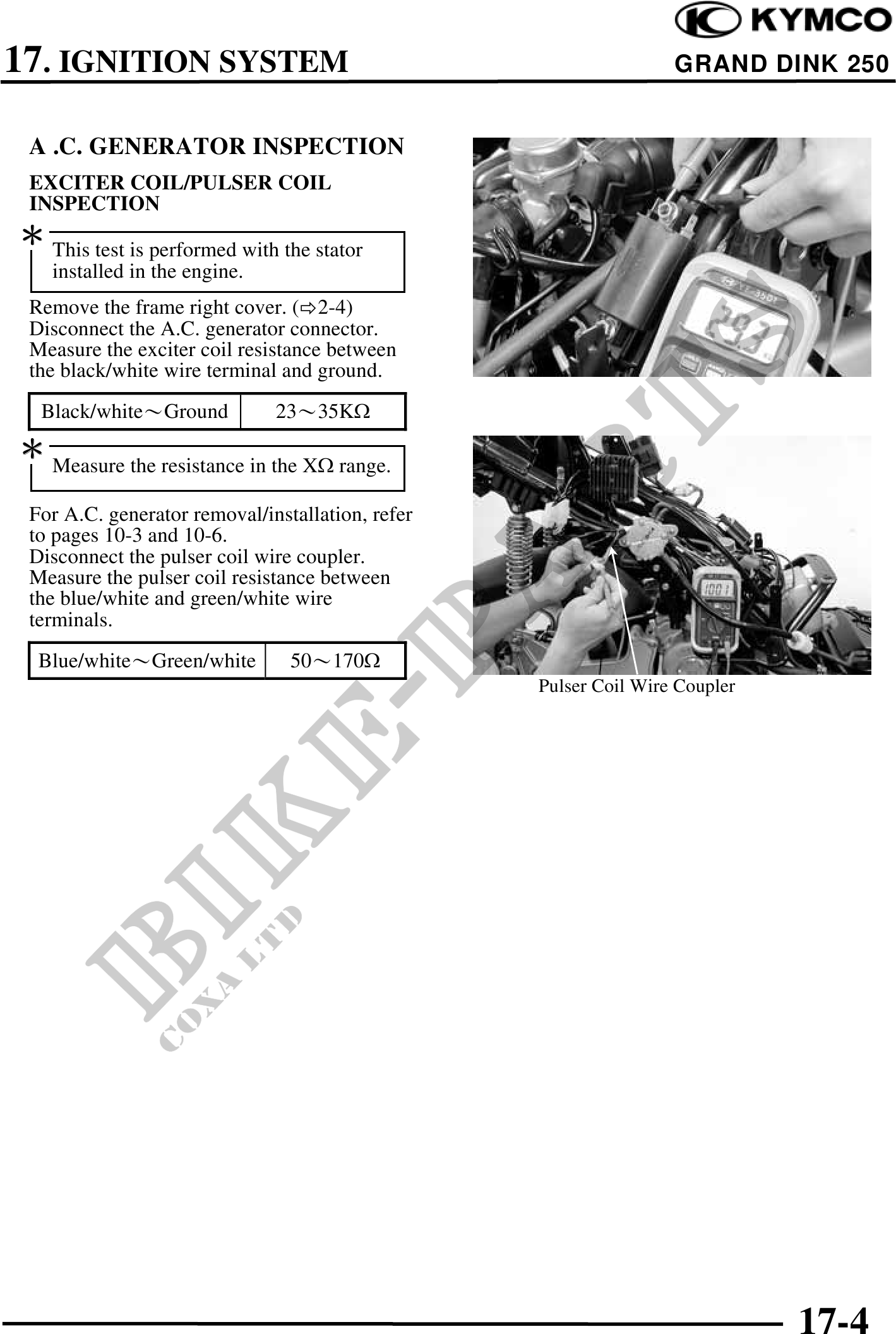
This test is performed with the stator
installed in the engine.
Remove the frame right cover. ( 2-4)
Disconnect the A.C. generator connector.
Measure the exciter coil resistance between
the black/white wire terminal and ground.
Black/whiteGround 2335K
Measure the resistance in the X range.
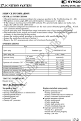
For A.C. generator removal/installation, refer
to pages 10-3 and 10-6.
Disconnect the pulser coil wire coupler.
Measure the pulser coil resistance between
the blue/white and green/white wire
terminals.
Blue/whiteGreen/white 50170
Pulser Coil Wire Coupler
17-4