Choose your country
We work in partnership with many official Kymco dealers around the world.
You can select the country of your choice from the list below, whatever your choice, we can deliver worldwide!
19. SWITCHES/HORN/FUELUNIT/THERMOSTATICSWITCH
/TEMPERATUREGAUGE/INSTRUMENTS/LIGHTS GRAND DINK 250
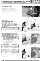
HORN INSPECTION
Remove the front upper cover. ( 2-5)
Disconnect the horn wire couplers.
The horn is normal if it sounds when a 12V
battery is connected across the horn wire
terminals.
Horn
Upper
FUEL UNIT
FUEL UNIT INSPECTION
Remove the fuel unit.
Disconnect the fuel unit wire connectors.
Measure the resistance between the fuel unit
wire terminals with the float at upper and
lower positions.
Wire Terminals Upper Lower
Y/WL/W 0.81.2K 70130
Lower
FUEL METER INSPECTION Fuel Unit
Connect the fuel unit wire connectors and
turn the ignition switch "ON".
Before performing the following test,
operate the turn signals to determine that
the battery circuit is normal.
Check the fuel meter LCD for correct
indication by moving the fuel unit float up
and down.
Float Position LCD Display Upper Fuel Full
Upper Much (Full)
Lower Less (Empty)
Wire Terminals LCD Display
Free From Much to Less
Apply From Less to Much
The fuel meter is normal if it operates as
above indicated. If not, check for loosely
tightened nuts, poorly connected terminals or
shorted wires.
Lower . Fuel Empty
19-5