grand dink 250 Workshop-manual : Page 218

Microfiches
Image preview

Page 216

Image preview

Page 217

Image preview

Page 219

Image preview

Page 220

1 5 10 15 20 25 30 35 40 45 50 55 60 65 70 75 80 85 90 95 100 105 110 115 120 125 130 135 140 145 150 155 160 165 170 175 180 185 190 195 200 205 210 215 220
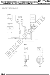
          19. SWITCHES/HORN/FUELUNIT/THERMOSTATICSWITCH
   /TEMPERATUREGAUGE/INSTRUMENTS/LIGHTS                                      GRAND DINK 250


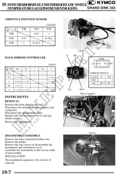
 THROTTLE POSTTION SENSOR

                                             Unit:K
                     V/R        V/G          V/B
    V/R                         4~6           
    V/G              4~6                     0~51
    V/B                         0~51

                                                                    T.P.S.
                                                        V     B/L       G
 BACK MIRROR CONTROLLER

                                              Unit:
           W/Y         Y/L      V      B/L       G

   W/Y                                           

   Y/L    5.8~11M                             0.2~0.8

    V     420~780K   9.3~17M                  9.3~17M

   B/L     7~13M                                 

    G     5.8~11M     0.2~0.8                           Y/L          W/Y
                                                                      Wire Couplers
 INSTRUMENTS
 REMOVAL
 Remove the front upper cover. ( 2-5)
 Disconnect the instrument wire couplers and
 connectors.
 Disconnect the speedometer cable.
 Remove the four instrument cover and leg
 shield screws.
 Remove the instruments.


                                                                             Screws
 DISASSEMBLY/ASSEMBLY
 Remove the three instrument holder nuts.
 Remove the holder.
 Remove the four screws to disassemble the
 instruments and instrument cover.
 Assemble the instruments in the reverse order
 of disassembly.
 INSTALLATION
 The installation sequence is the reverse of
 removal.


19-7