Choose your country
We work in partnership with many official Kymco dealers around the world.
You can select the country of your choice from the list below, whatever your choice, we can deliver worldwide!
16. INSTRUMENT/SWITCHES/LIGHTS SUPER8 50 2T
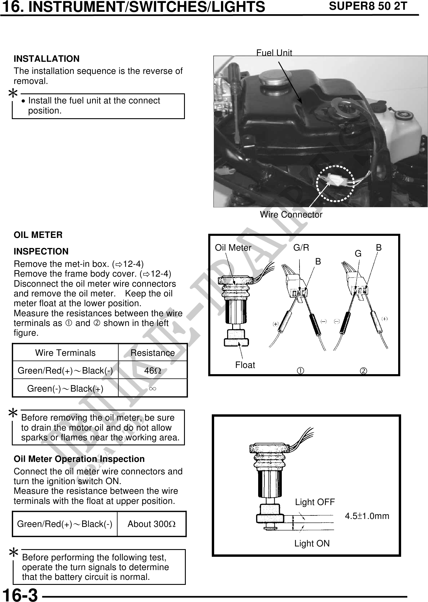
Fuel Unit
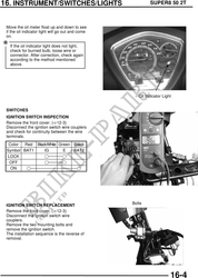
INSTALLATION
The installation sequence is the reverse of
removal.
· Install the fuel unit at the connect
position.
Wire Connector
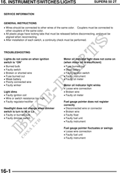
OIL METER
INSPECTION Oil Meter G/R B
G
Remove the met-in box. ( 12-4) B
Remove the frame body cover. ( 12-4)
Disconnect the oil meter wire connectors
and remove the oil meter. Keep the oil
meter float at the lower position.
Measure the resistances between the wire
terminals as and shown in the left
figure.
Wire Terminals Resistance
Float
Green/Red(+)Black(-) 46
Green(-)Black(+)
Before removing the oil meter, be sure
to drain the motor oil and do not allow
sparks or flames near the working area.
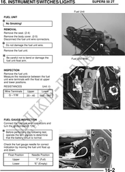
Oil Meter Operation Inspection
Connect the oil meter wire connectors and
turn the ignition switch ON.
Measure the resistance between the wire
terminals with the float at upper position. Light OFF
4.51.0mm
Light OFF
Green/Red(+)Black(-) About 300
Light ON
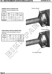
Before performing the following test,
operate the turn signals to determine
that the battery circuit is normal.
16-3