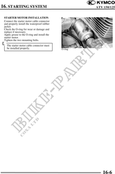
16. STARTING SYSTEM ATV 1540/125
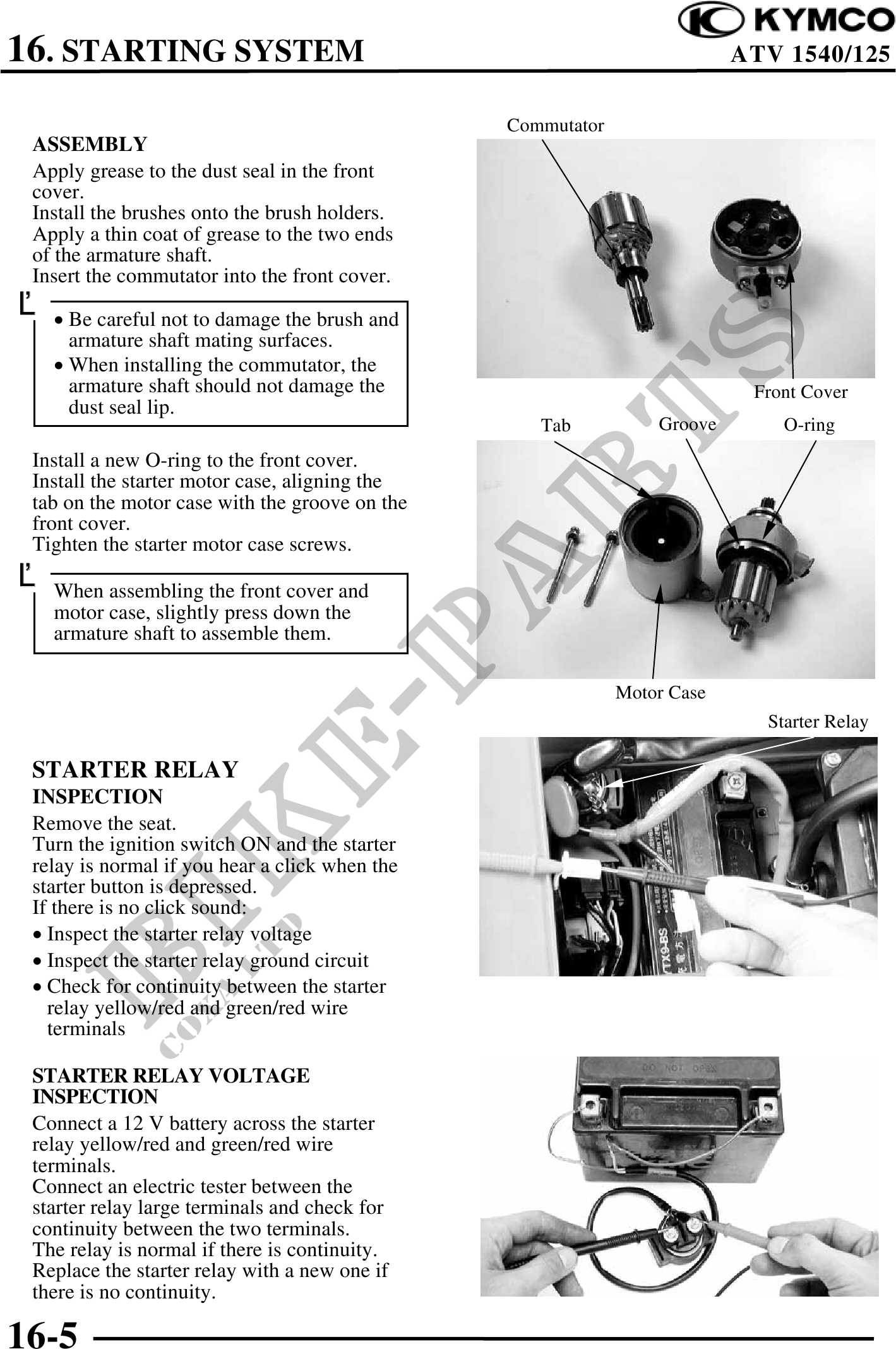
Commutator
ASSEMBLY
Apply grease to the dust seal in the front
cover.
Install the brushes onto the brush holders.
Apply a thin coat of grease to the two ends
of the armature shaft.
Insert the commutator into the front cover.
· Be careful not to damage the brush and
armature shaft mating surfaces.
· When installing the commutator, the
armature shaft should not damage the Front Cover
dust seal lip.
Tab Groove O-ring
Install a new O-ring to the front cover.
Install the starter motor case, aligning the
tab on the motor case with the groove on the
front cover.
Tighten the starter motor case screws.
When assembling the front cover and
motor case, slightly press down the
armature shaft to assemble them.
Motor Case
Starter Relay
STARTER RELAY
INSPECTION
Remove the seat.
Turn the ignition switch ON and the starter
relay is normal if you hear a click when the
starter button is depressed.
If there is no click sound:
· Inspect the starter relay voltage
· Inspect the starter relay ground circuit
· Check for continuity between the starter
relay yellow/red and green/red wire
terminals
STARTER RELAY VOLTAGE
INSPECTION
Connect a 12 V battery across the starter
relay yellow/red and green/red wire
terminals.
Connect an electric tester between the
starter relay large terminals and check for
continuity between the two terminals.
The relay is normal if there is continuity.
Replace the starter relay with a new one if
there is no continuity.
16-5