Choose your country
We work in partnership with many official Kymco dealers around the world.
You can select the country of your choice from the list below, whatever your choice, we can deliver worldwide!
3. INSPECTION/ADJUSTMENT ATV 150/125
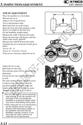
TOE-IN ADJUSTMENT A
Place the machine on a level place.
Measure the toe-in
Adjust if out of specification.
Toe-in measurement steps:
Mark both front tire tread centers.
Raise the front end of the machine so that
there is no weight on the front tires.
Fix the handlebar straight ahead. B
Measure the width A between the marks.
Rotate the front tires 180 degrees until the
marks come exactly opposite.
Measure the width B between the marks.
Calculate the toe-in using the formula given
below.
Toe-in = BA
Toe-in: 015 mm (00.6 in)
If the toe-in is incorrect, adjust the toe-in
Tie-rod
Adjust the toe-in step:
Mark both tie-rods ends.
This reference point will be needed during
adjustment.
Loosen the lock nuts (tie-rod end) of both
tie-rods
The same number of turns should be given
to both tie-rods right and left until the
specified toe-in is obtained, so that the
lengths of the rods will be kept the same. Tie-rod End Nuts
Torque: 3 kgf-m (30 N-m, 22 lbf-ft)
· Be sure that both tie-rod are turned the
same amount. If not, the machine will
drift tight or left even though the
handlebar is positioned straight which
may lead to mishandling and accident.
· After setting the toe-in to specification,
run the machine slowly for some
distance with hands placed lightly on
the handlebar and check that the
handlebar responds correctly. If not,
turn either the right or left tie-rod
within the toe-in specification.
3-13