Choose your country
We work in partnership with many official Kymco dealers around the world.
You can select the country of your choice from the list below, whatever your choice, we can deliver worldwide!
6. ENGINE REMOVAL/INSTALLATION MXU 300/250
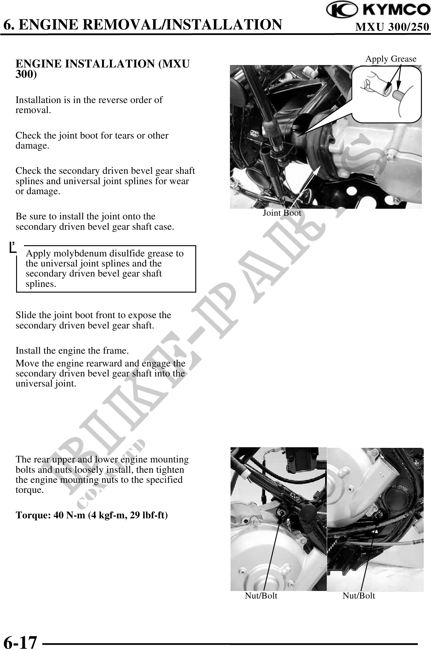
Apply Grease
ENGINE INSTALLATION (MXU
300)
Installation is in the reverse order of
removal.
Check the joint boot for tears or other
damage.
Check the secondary driven bevel gear shaft
splines and universal joint splines for wear
or damage.
Be sure to install the joint onto the Joint Boot
secondary driven bevel gear shaft case.
Apply molybdenum disulfide grease to
the universal joint splines and the
secondary driven bevel gear shaft
splines.
Slide the joint boot front to expose the
secondary driven bevel gear shaft.
Install the engine the frame.
Move the engine rearward and engage the
secondary driven bevel gear shaft into the
universal joint.
The rear upper and lower engine mounting
bolts and nuts loosely install, then tighten
the engine mounting nuts to the specified
torque.
Torque: 40 N-m (4 kgf-m, 29 lbf-ft)
Nut/Bolt Nut/Bolt
6-17