Choose your country
We work in partnership with many official Kymco dealers around the world.
You can select the country of your choice from the list below, whatever your choice, we can deliver worldwide!

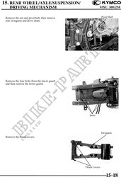
15. REAR WHEEL/AXLE/SUSPENSION/
DRIVING MECHANISM MXU 300/250
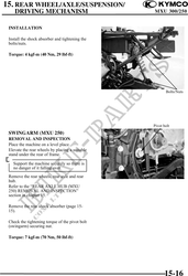
INSTALLATION
Install the shock absorber and tightening the
bolts/nuts.
Torque: 4 kgf-m (40 Nm, 29 lbf-ft)
Bolts/Nuts
Pivot bolt
SWINGARM (MXU 250)
REMOVAL AND INSPECTION
Place the machine on a level place.
Elevate the rear wheels by placing a suitable
stand under the rear of frame.
Support the machine securely so there is
no danger of it falling over.
Remove the rear wheels, rear axle and rear
hub.
Refer to the "REAR AXLE HUB (MXU
250) REMOVAL AND INSPECTION"
section in chapter 15.
Remove the rear shock absorber (page 15-
15).
Check the tightening torque of the pivot bolt
(swingarm) securing nut.
Torque: 7 kgf-m (70 Nm, 50 lbf-ft)
15-16