Choose your country
We work in partnership with many official Kymco dealers around the world.
You can select the country of your choice from the list below, whatever your choice, we can deliver worldwide!
6. CYLINDER HEAD/VALVES ZING II 125
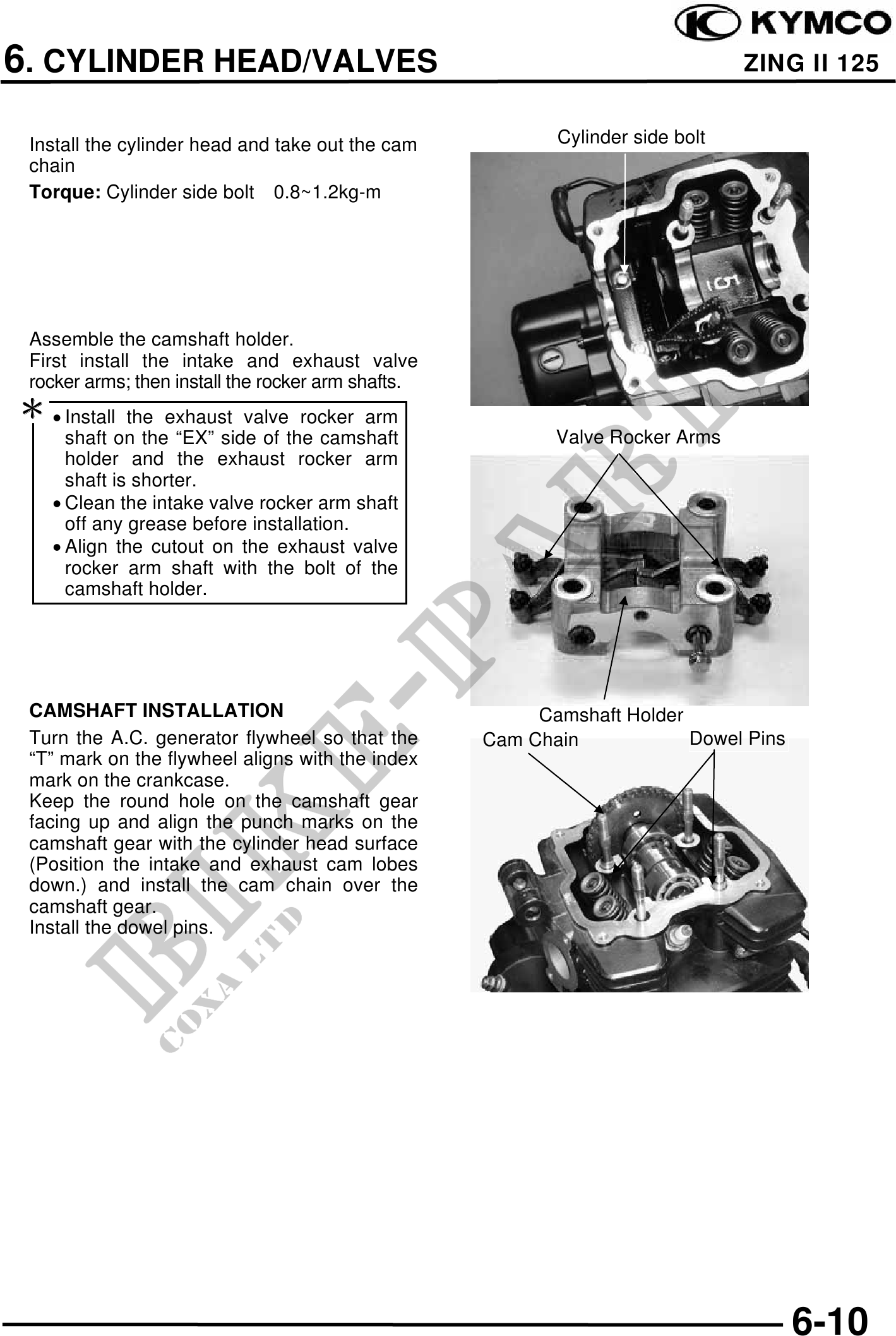
Install the cylinder head and take out the cam Cylinder side bolt
chain
Torque: Cylinder side bolt 0.8~1.2kg-m
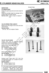
Assemble the camshaft holder.
First install the intake and exhaust valve
rocker arms; then install the rocker arm shafts.
· Install the exhaust valve rocker arm
shaft on the "EX" side of the camshaft Valve Rocker Arms
holder and the exhaust rocker arm
shaft is shorter.
· Clean the intake valve rocker arm shaft
off any grease before installation.
· Align the cutout on the exhaust valve
rocker arm shaft with the bolt of the
camshaft holder.
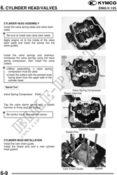
CAMSHAFT INSTALLATION Camshaft Holder
Turn the A.C. generator flywheel so that the Cam Chain Dowel Pins
"T" mark on the flywheel aligns with the index
mark on the crankcase.
Keep the round hole on the camshaft gear
facing up and align the punch marks on the
camshaft gear with the cylinder head surface
(Position the intake and exhaust cam lobes
down.) and install the cam chain over the
camshaft gear.
Install the dowel pins.
6-10