Choose your country
We work in partnership with many official Kymco dealers around the world.
You can select the country of your choice from the list below, whatever your choice, we can deliver worldwide!
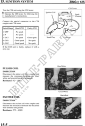
15. IGNITION SYSTEM ZING125
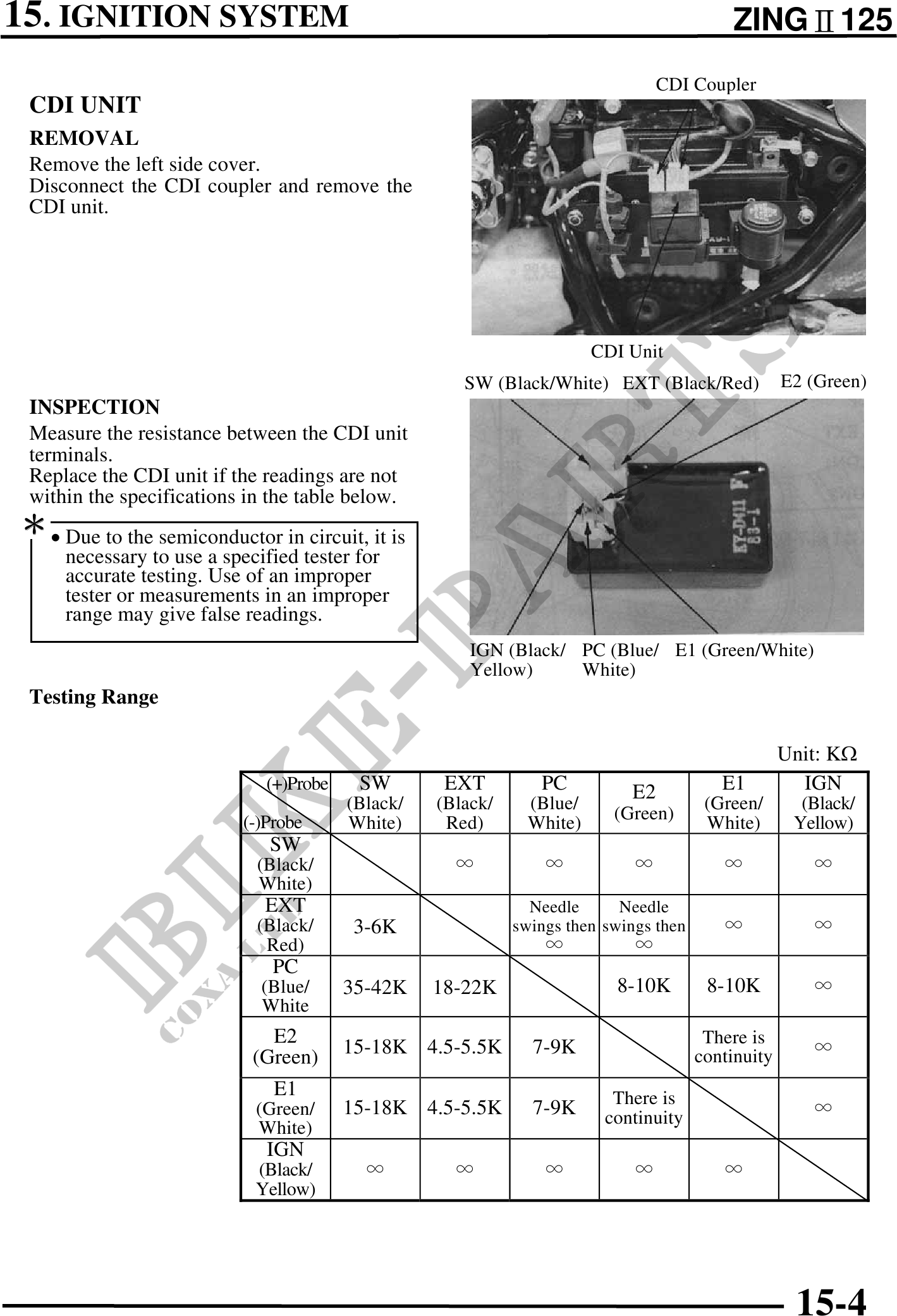
CDI Coupler
CDI UNIT
REMOVAL
Remove the left side cover.
Disconnect the CDI coupler and remove the
CDI unit.
CDI Unit
SW (Black/White) EXT (Black/Red) E2 (Green)
INSPECTION
Measure the resistance between the CDI unit
terminals.
Replace the CDI unit if the readings are not
within the specifications in the table below.
· Due to the semiconductor in circuit, it is
necessary to use a specified tester for
accurate testing. Use of an improper
tester or measurements in an improper
range may give false readings.
IGN (Black/ PC (Blue/ E1 (Green/White)
Yellow) White)
Testing Range
Unit: K
(+)Probe SW EXT PC E2 E1 IGN
(Black/ (Black/ (Blue/ (Green/ (Black/
(-)Probe White) Red) White) (Green) White) Yellow)
SW
(Black/
White)
EXT Needle Needle
(Black/ 3-6K swings then swings then
Red)
PC
(Blue/ 35-42K 18-22K 8-10K 8-10K
White
E2 There is
15-18K 4.5-5.5K 7-9K continuity
(Green)
E1 There is
(Green/ 15-18K 4.5-5.5K 7-9K continuity
White)
IGN
(Black/
Yellow)
15-4