Choose your country
We work in partnership with many official Kymco dealers around the world.
You can select the country of your choice from the list below, whatever your choice, we can deliver worldwide!
7. CYLINDER HEAD/VALVES MXU 300/250
SERVICE INFORMATION
GENERAL INSTRUCTIONS
· The cylinder head can be serviced with the engine installed in the frame.
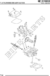
· When assembling, apply molybdenum disulfide grease or engine oil to the valve guide movable
parts, valve arm and camshaft sliding surfaces for initial lubrication.
· The camshaft is lubricated by engine oil through the cylinder head engine oil passages. Clean and
unclog the oil passages before assembling the cylinder head.
· After disassembly, clean the removed parts and dry them with compressed air before inspection.
· After removal, mark and arrange the removed parts in order. When assembling, install them in
the reverse order of removal.
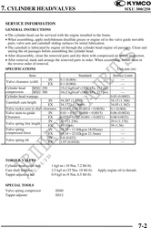
SPECIFICATIONS Unit mm (in)
Item Standard Service Limit
IN 0.1 (0.004)
Valve clearance (cold)
EX 0.1 (0.004)
Cylinder head MXU 250 152 kgf/cm (1500 kPa, 213 psi)
compression MXU 300 162 kgf/cm (1600 kPa, 227 psi)
Cylinder head warpage 0.05 (0.0002)
IN 34.287 (1.3715) 34.15 (1.366)
Camshaft cam height
EX 34.1721 (1.3669) 34.05 (1.362)
Valve rocker arm to shaft clearance 0.0340.09 (0.00140.0036) 0.1 (0.004)
Valve stem-to-guide IN 0.010.037 (0.0040.0015) 0.06 (0.0024)
Clearance EX 0.0250.052 (0.0010.0021) 0.08 0.0032)
IN 30.9 (1.236) 29.4 (1.176)
Valve spring free length
EX 41 (1.64) 39 (1.56)
Valve spring IN 10.2011.84kg(at 18.05mm)
compressed force EX 19.1422.02kg(at 21.5mm)
IN 0.8 (0.032)
Valve spring tilt
EX 1.07 (0.0428)
TORQUE VALUES
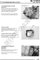
Cylinder head cover bolt 1 kgf-m ( 10 Nm, 7.2 lbf-ft)
Cam shaft hold nut 2.5 kgf-m (25 Nm, 18 lbf-ft) Apply engine oil to threads
Tappet adjusting nut 0.9 kgf-m (9 Nm, 6.5 lbf-ft)
SPECIAL TOOLS
Valve spring compressor E040
Tappet adjuster E012
7-2