Choose your country
We work in partnership with many official Kymco dealers around the world.
You can select the country of your choice from the list below, whatever your choice, we can deliver worldwide!
13. BRAKE SYSTEM MXU 300/250
BRAKE DISK
Measure the brake disk thickness.
Service Limit: 3 mm (0.12 in)
Measure the brake disk run out.
Service Limit: 0.3 mm (0.012 in)
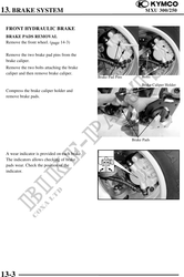
INSTALLATION
Reverse the "BRAKE PADS REMOVAL"
procedures.
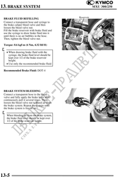
Torque:
Brake pad pin bolt:
1.8 kgf-m (18 Nm, 13 lbf-ft)
Brake caliper mounting bolt (replace a
new one): 3.2 kgf-m (32 Nm, 25 lbf-ft)
FRONT BRAKE FLUID
CHANGE/AIR BLEED
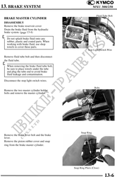
BRAKE FLUID DRAINING
Place the machine on the level ground and
set the handlebar upright.
Remove the two screws attaching the brake
fluid reservoir cap.
Use shop towels to cover plastic parts
and coated surfaces to avoid damage Screws
caused by splash of brake fluid.
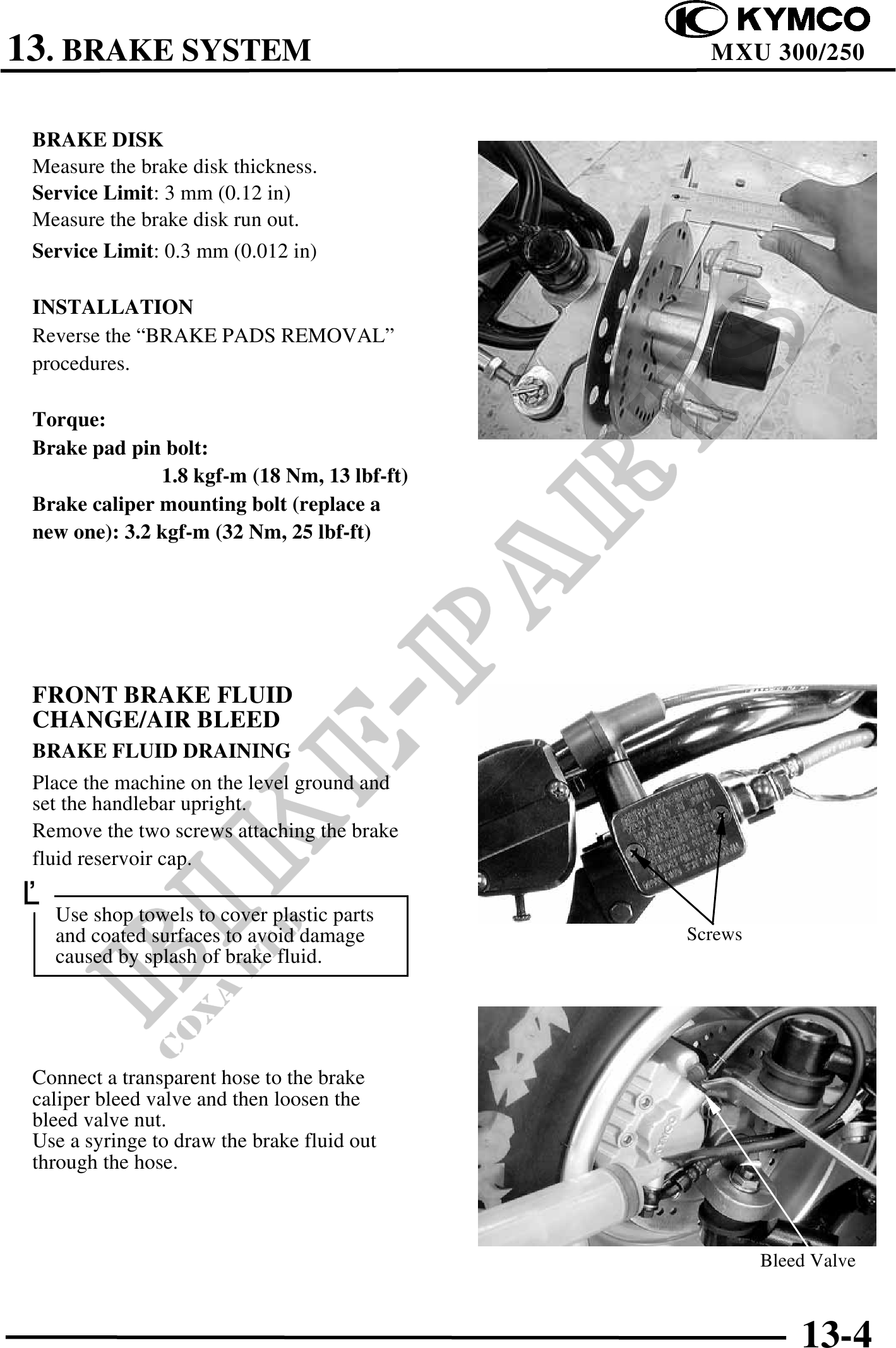
Connect a transparent hose to the brake
caliper bleed valve and then loosen the
bleed valve nut.
Use a syringe to draw the brake fluid out
through the hose.
Bleed Valve
13-4