My Cart

| Description | Part number | Qty |
|---|
| Description | Part number | Qty |
|---|
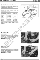
15. IGNITION SYSTEM ZING125
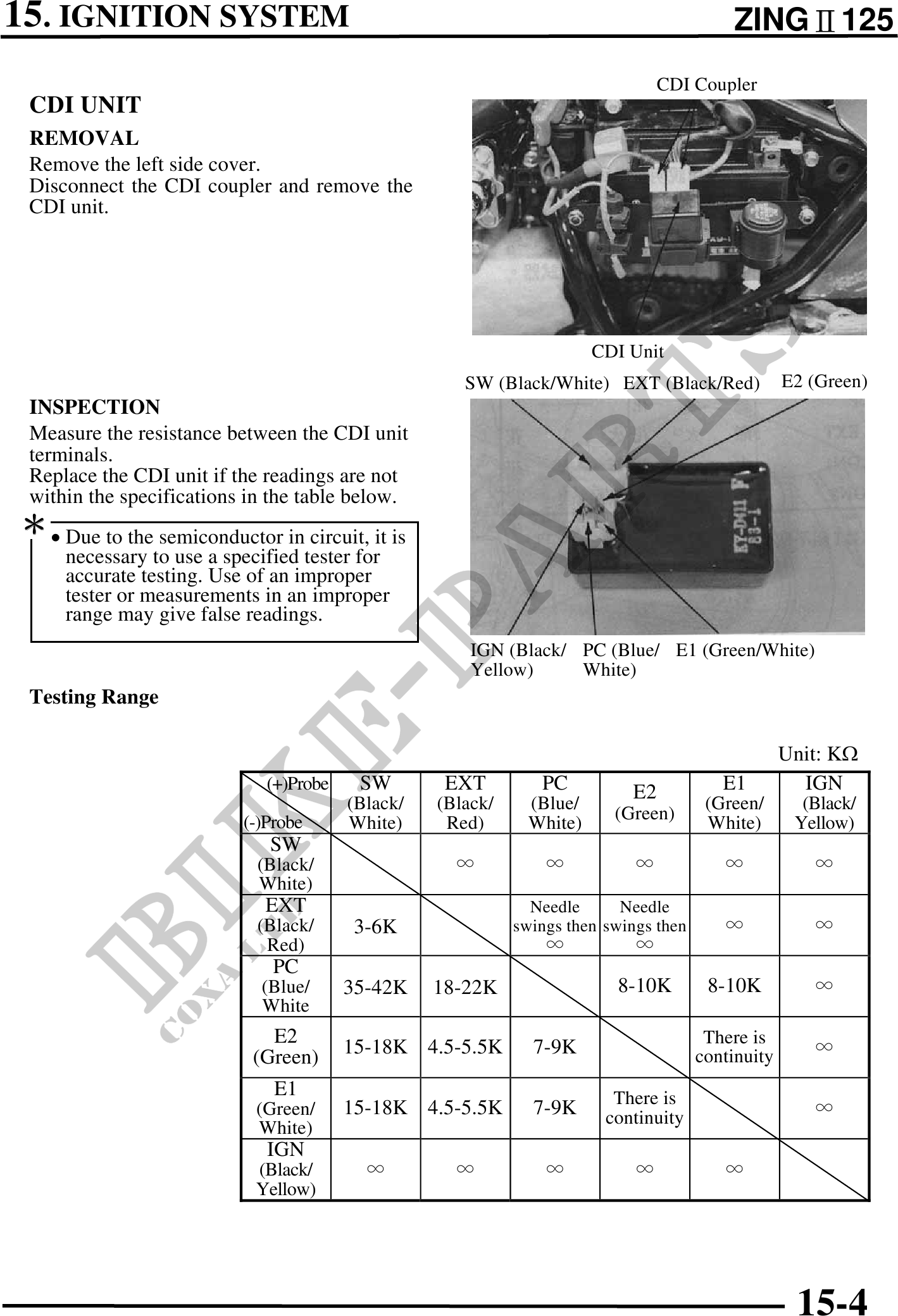
CDI Coupler
CDI UNIT
REMOVAL
Remove the left side cover.
Disconnect the CDI coupler and remove the
CDI unit.
CDI Unit
SW (Black/White) EXT (Black/Red) E2 (Green)
INSPECTION
Measure the resistance between the CDI unit
terminals.
Replace the CDI unit if the readings are not
within the specifications in the table below.
· Due to the semiconductor in circuit, it is
necessary to use a specified tester for
accurate testing. Use of an improper
tester or measurements in an improper
range may give false readings.
IGN (Black/ PC (Blue/ E1 (Green/White)
Yellow) White)
Testing Range
Unit: K
(+)Probe SW EXT PC E2 E1 IGN
(Black/ (Black/ (Blue/ (Green/ (Black/
(-)Probe White) Red) White) (Green) White) Yellow)
SW
(Black/
White)
EXT Needle Needle
(Black/ 3-6K swings then swings then
Red)
PC
(Blue/ 35-42K 18-22K 8-10K 8-10K
White
E2 There is
15-18K 4.5-5.5K 7-9K continuity
(Green)
E1 There is
(Green/ 15-18K 4.5-5.5K 7-9K continuity
White)
IGN
(Black/
Yellow)
15-4