Choose your country
We work in partnership with many official Kymco dealers around the world.
You can select the country of your choice from the list below, whatever your choice, we can deliver worldwide!
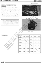
16. CHARGING SYSTEM ZING125
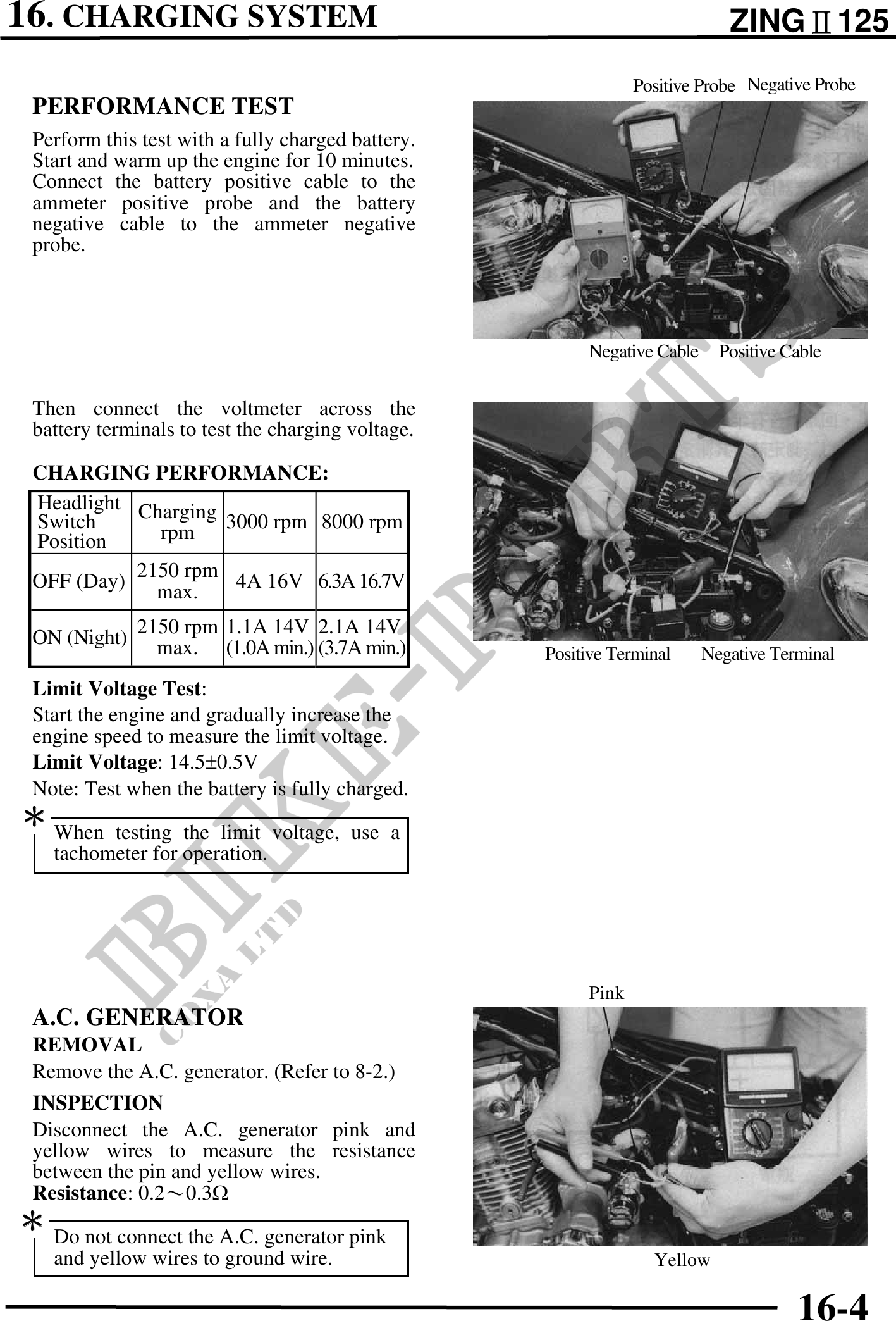
Positive Probe Negative Probe
PERFORMANCE TEST
Perform this test with a fully charged battery.
Start and warm up the engine for 10 minutes.
Connect the battery positive cable to the
ammeter positive probe and the battery
negative cable to the ammeter negative
probe.
Negative Cable Positive Cable
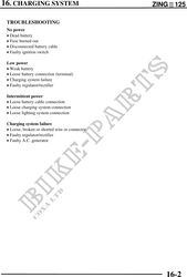
Then connect the voltmeter across the
battery terminals to test the charging voltage.
CHARGING PERFORMANCE:
Headlight Charging
Switch
Position rpm 3000 rpm 8000 rpm
OFF (Day) 2150 rpm 4A 16V 6.3A 16.7V
max.
ON (Night) 2150 rpm 1.1A 14V 2.1A 14V
max. (1.0A min.) (3.7A min.) Positive Terminal Negative Terminal
Limit Voltage Test:
Start the engine and gradually increase the
engine speed to measure the limit voltage.
Limit Voltage: 14.50.5V
Note: Test when the battery is fully charged.
When testing the limit voltage, use a
tachometer for operation.
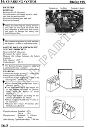
Pink
A.C. GENERATOR
REMOVAL
Remove the A.C. generator. (Refer to 8-2.)
INSPECTION
Disconnect the A.C. generator pink and
yellow wires to measure the resistance
between the pin and yellow wires.
Resistance: 0.20.3
Do not connect the A.C. generator pink
and yellow wires to ground wire. Yellow
16-4