Choose your country
We work in partnership with many official Kymco dealers around the world.
You can select the country of your choice from the list below, whatever your choice, we can deliver worldwide!
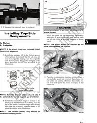
Inspecting Camshaft Bearing
Journal
1. Inspect the bearing journal for scoring, seizure
marks, or pitting.
2. If excessive scoring, seizure marks, or pitting is
found, the cylinder head assembly must be
replaced.
Measuring Camshaft to
Cylinder Head Clearance
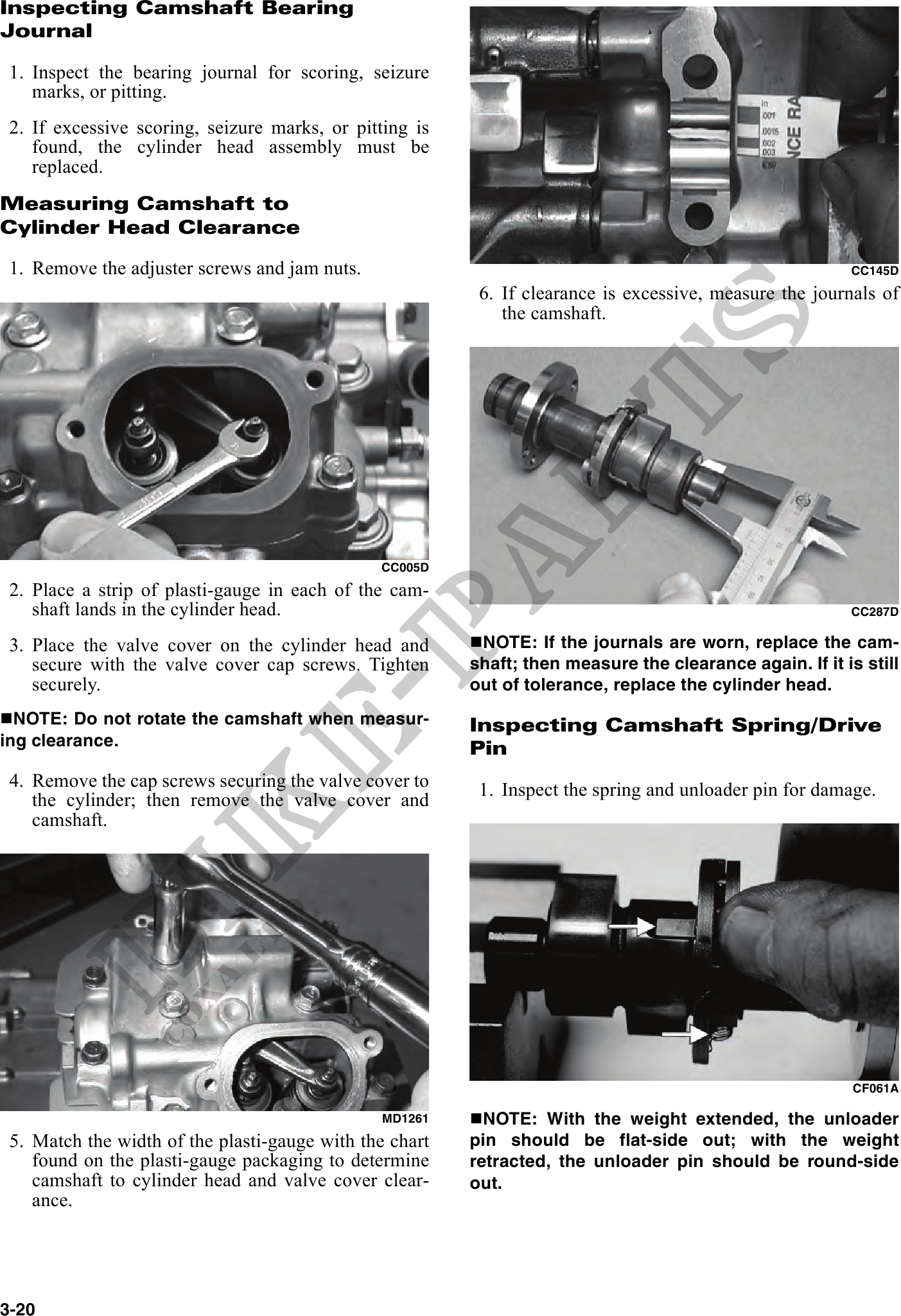
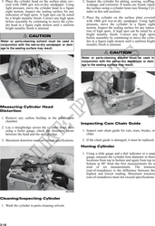
1. Remove the adjuster screws and jam nuts. CC145D
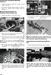
6. If clearance is excessive, measure the journals of
the camshaft.
CC005D
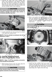
2. Place a strip of plasti-gauge in each of the cam-
shaft lands in the cylinder head. CC287D
3. Place the valve cover on the cylinder head and NOTE: If the journals are worn, replace the cam-
secure with the valve cover cap screws. Tighten shaft; then measure the clearance again. If it is still
securely. out of tolerance, replace the cylinder head.
NOTE: Do not rotate the camshaft when measur- Inspecting Camshaft Spring/Drive
ing clearance. Pin
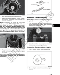
4. Remove the cap screws securing the valve cover to 1. Inspect the spring and unloader pin for damage.
the cylinder; then remove the valve cover and
camshaft.
CF061A
MD1261 NOTE: With the weight extended, the unloader
5. Match the width of the plasti-gauge with the chart pin should be flat-side out; with the weight
found on the plasti-gauge packaging to determine retracted, the unloader pin should be round-side
camshaft to cylinder head and valve cover clear- out.
ance.
3-20