Choose your country
We work in partnership with many official Kymco dealers around the world.
You can select the country of your choice from the list below, whatever your choice, we can deliver worldwide!
Fuel/Lubrication/ Carburetor Schematic
Cooling
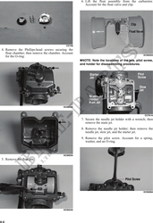
NOTE: KYMCO recommends the use of new
gaskets, lock nuts, and seals and lubricating all
internal components when servicing the
engine/transmission.
NOTE: Some photographs and illustrations
used in this section are used for clarity purposes
only and are not designed to depict actual
conditions.
NOTE: Critical torque specifications are located
in Section 1.
SPECIAL TOOLS
A number of special tools must be available to the KEY
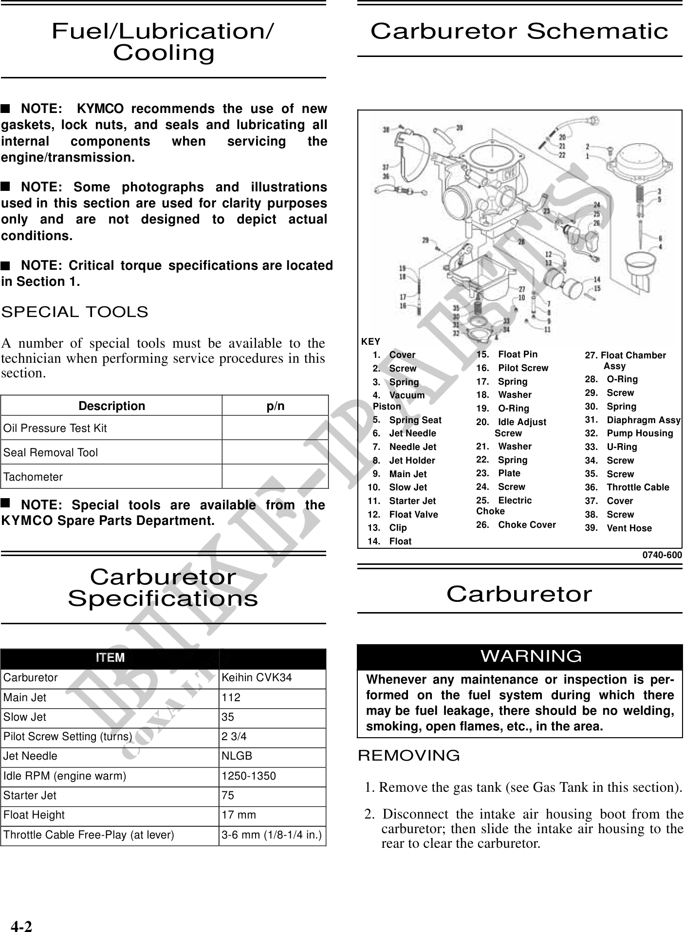
1. Cover 15. Float Pin 27. Float Chamber
technician when performing service procedures in this Assy
2. Screw 16. Pilot Screw
section. 17. Spring 28. O-Ring
3. Spring
4. Vacuum 18. Washer 29. Screw
Description p/n Piston 19. O-Ring 30. Spring
5. Spring Seat 20. Idle Adjust 31. Diaphragm Assy
Oil Pressure Test Kit 6. Jet Needle Screw 32. Pump Housing
7. Needle Jet 21. Washer 33. U-Ring
Seal Removal Tool
8. Jet Holder 22. Spring 34. Screw
Tachometer 9. Main Jet 23. Plate 35. Screw
10. Slow Jet 24. Screw 36. Throttle Cable
11. Starter Jet 25. Electric 37. Cover
NOTE: Special tools are available from the Choke
12. Float Valve 38. Screw
KYMCO Spare Parts Department. 13. Clip 26. Choke Cover 39. Vent Hose
14. Float
0740-600
Carburetor
Specifications Carburetor
ITEM WARNING
Carburetor Keihin CVK34 Whenever any maintenance or inspection is per-
Main Jet 112 formed on the fuel system during which there
Slow Jet 35
may be fuel leakage, there should be no welding,
smoking, open flames, etc., in the area.
Pilot Screw Setting (turns) 2 3/4
Jet Needle NLGB REMOVING
Idle RPM (engine warm) 1250-1350
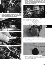
1. Remove the gas tank (see Gas Tank in this section).
Starter Jet 75
Float Height 17 mm 2. Disconnect the intake air housing boot from the
Throttle Cable Free-Play (at lever) 3-6 mm (1/8-1/4 in.) carburetor; then slide the intake air housing to the
rear to clear the carburetor.
4-2