Choose your country
We work in partnership with many official Kymco dealers around the world.
You can select the country of your choice from the list below, whatever your choice, we can deliver worldwide!
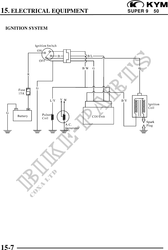
15. ELECTRICAL EQUIPMENT SUPER 9 50
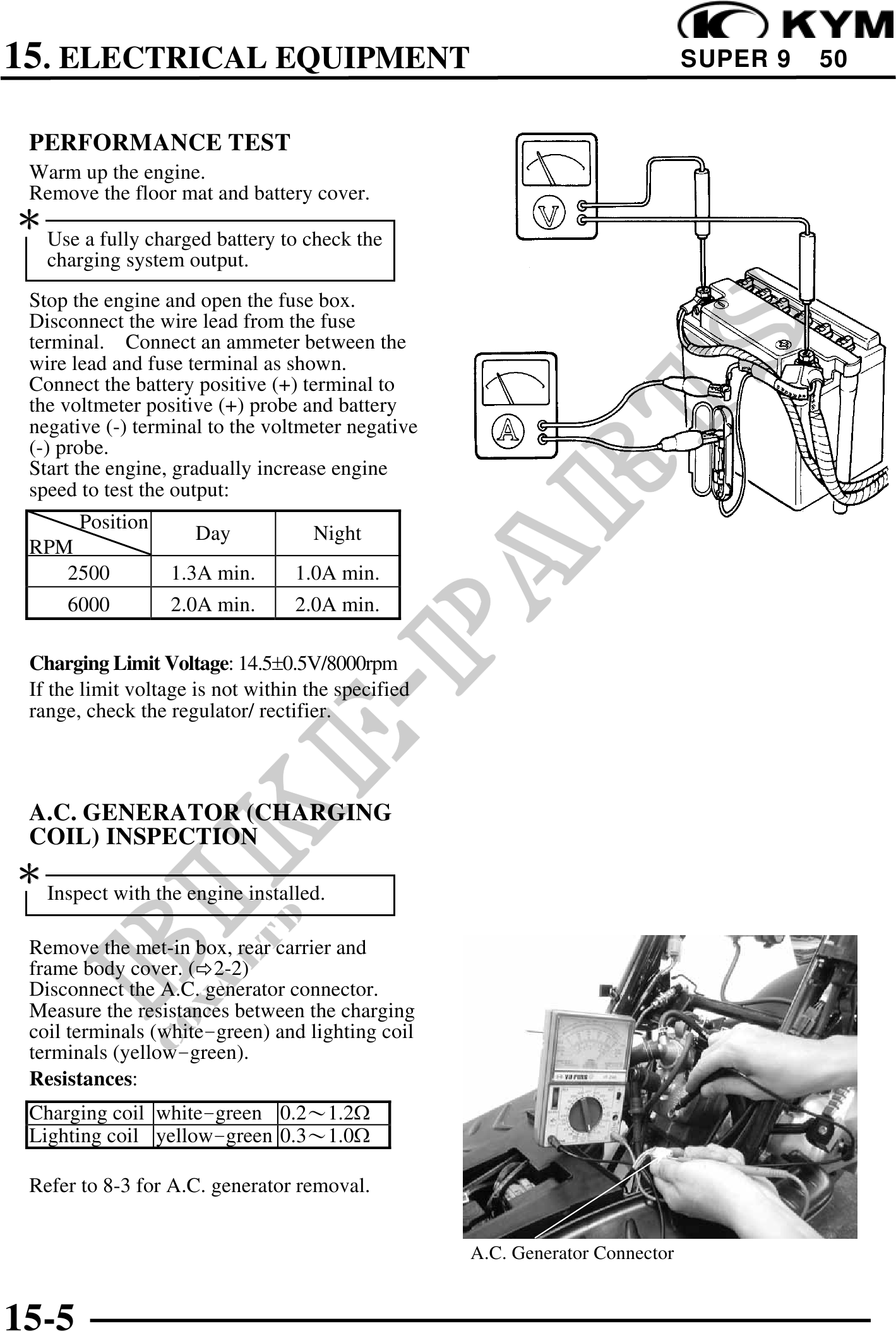
PERFORMANCE TEST
Warm up the engine.
Remove the floor mat and battery cover.
Use a fully charged battery to check the
charging system output.
Stop the engine and open the fuse box.
Disconnect the wire lead from the fuse
terminal. Connect an ammeter between the
wire lead and fuse terminal as shown.
Connect the battery positive (+) terminal to
the voltmeter positive (+) probe and battery
negative (-) terminal to the voltmeter negative
(-) probe.
Start the engine, gradually increase engine
speed to test the output:
Position
Day Night
RPM
2500 1.3A min. 1.0A min.
6000 2.0A min. 2.0A min.
Charging Limit Voltage: 14.50.5V/8000rpm
If the limit voltage is not within the specified
range, check the regulator/ rectifier.
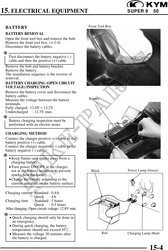
A.C. GENERATOR (CHARGING
COIL) INSPECTION
Inspect with the engine installed.
Remove the met-in box, rear carrier and
frame body cover. ( 2-2)
Disconnect the A.C. generator connector.
Measure the resistances between the charging
coil terminals (whitegreen) and lighting coil
terminals (yellowgreen).
Resistances:
Charging coil whitegreen 0.21.2
Lighting coil yellowgreen 0.31.0
Refer to 8-3 for A.C. generator removal.
A.C. Generator Connector
15-5