Choose your country
We work in partnership with many official Kymco dealers around the world.
You can select the country of your choice from the list below, whatever your choice, we can deliver worldwide!
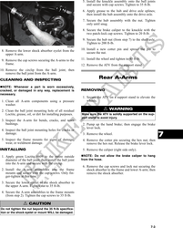
Suspension Front A-Arms
NOTE: Critical torque specifications are located REMOVING
in Section 1.
1. Secure the ATV on a support stand to elevate the
front wheels; then remove the wheels.
Shock Absorbers ! WARNING
Make sure the ATV is solidly supported on the sup-
port stand to avoid injury.
REMOVING
2. Remove the cotter pin from the nut. Discard the
1. Secure the ATV on a support stand to elevate the cotter pin.
wheels and to release load on the suspension.
3. Remove the nut securing the hub.
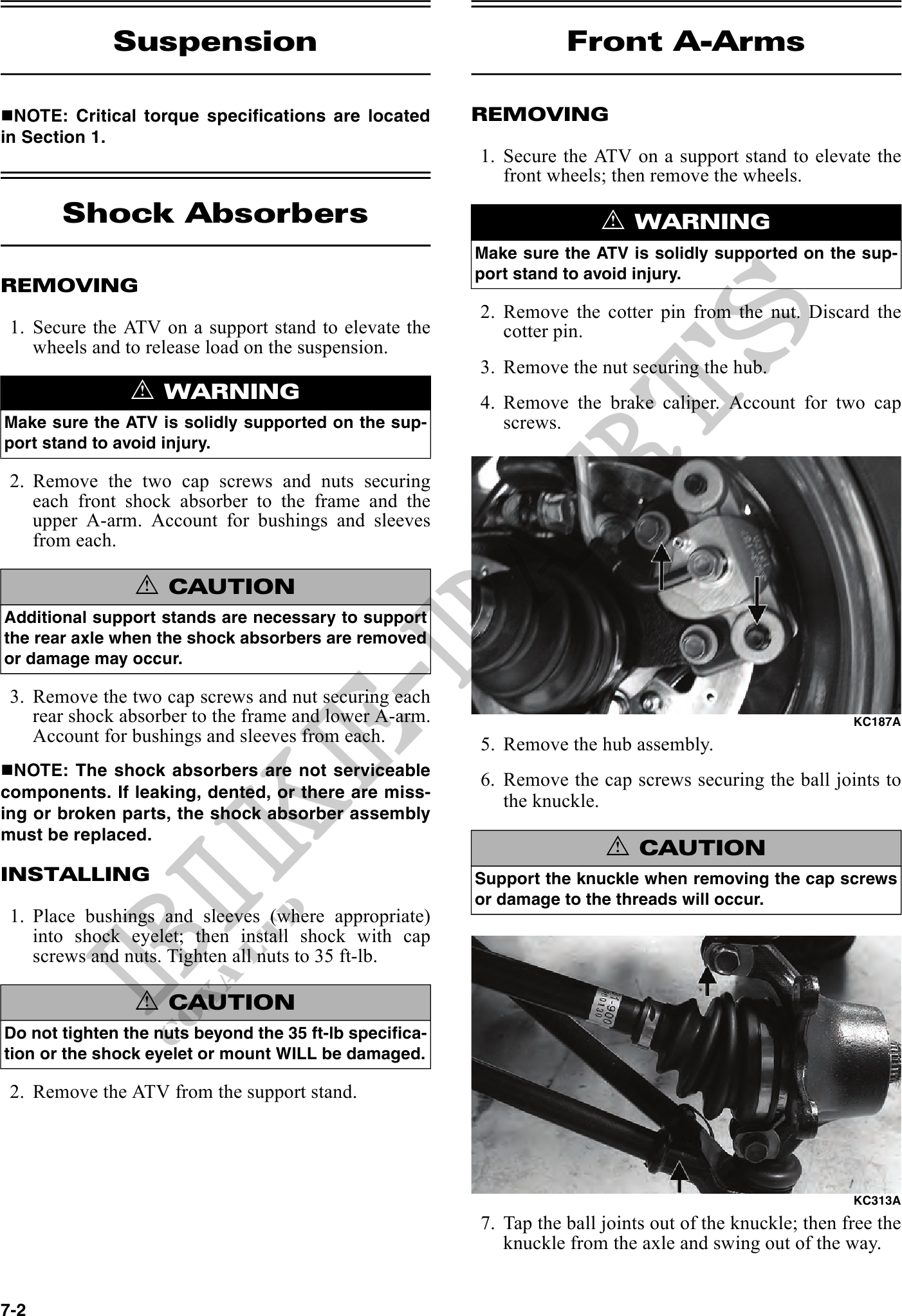
! WARNING 4. Remove the brake caliper. Account for two cap
Make sure the ATV is solidly supported on the sup- screws.
port stand to avoid injury.
2. Remove the two cap screws and nuts securing
each front shock absorber to the frame and the
upper A-arm. Account for bushings and sleeves
from each.
! CAUTION
Additional support stands are necessary to support
the rear axle when the shock absorbers are removed
or damage may occur.
3. Remove the two cap screws and nut securing each
rear shock absorber to the frame and lower A-arm. KC187A
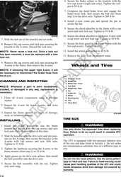
Account for bushings and sleeves from each. 5. Remove the hub assembly.
NOTE: The shock absorbers are not serviceable
6. Remove the cap screws securing the ball joints to
components. If leaking, dented, or there are miss- the knuckle.
ing or broken parts, the shock absorber assembly
must be replaced.
! CAUTION
INSTALLING Support the knuckle when removing the cap screws
or damage to the threads will occur.
1. Place bushings and sleeves (where appropriate)
into shock eyelet; then install shock with cap
screws and nuts. Tighten all nuts to 35 ft-lb.
! CAUTION
Do not tighten the nuts beyond the 35 ft-lb specifica-
tion or the shock eyelet or mount WILL be damaged.
2. Remove the ATV from the support stand.
KC313A
7. Tap the ball joints out of the knuckle; then free the
knuckle from the axle and swing out of the way.
7-2