Choose your country
We work in partnership with many official Kymco dealers around the world.
You can select the country of your choice from the list below, whatever your choice, we can deliver worldwide!
KC149A KC128
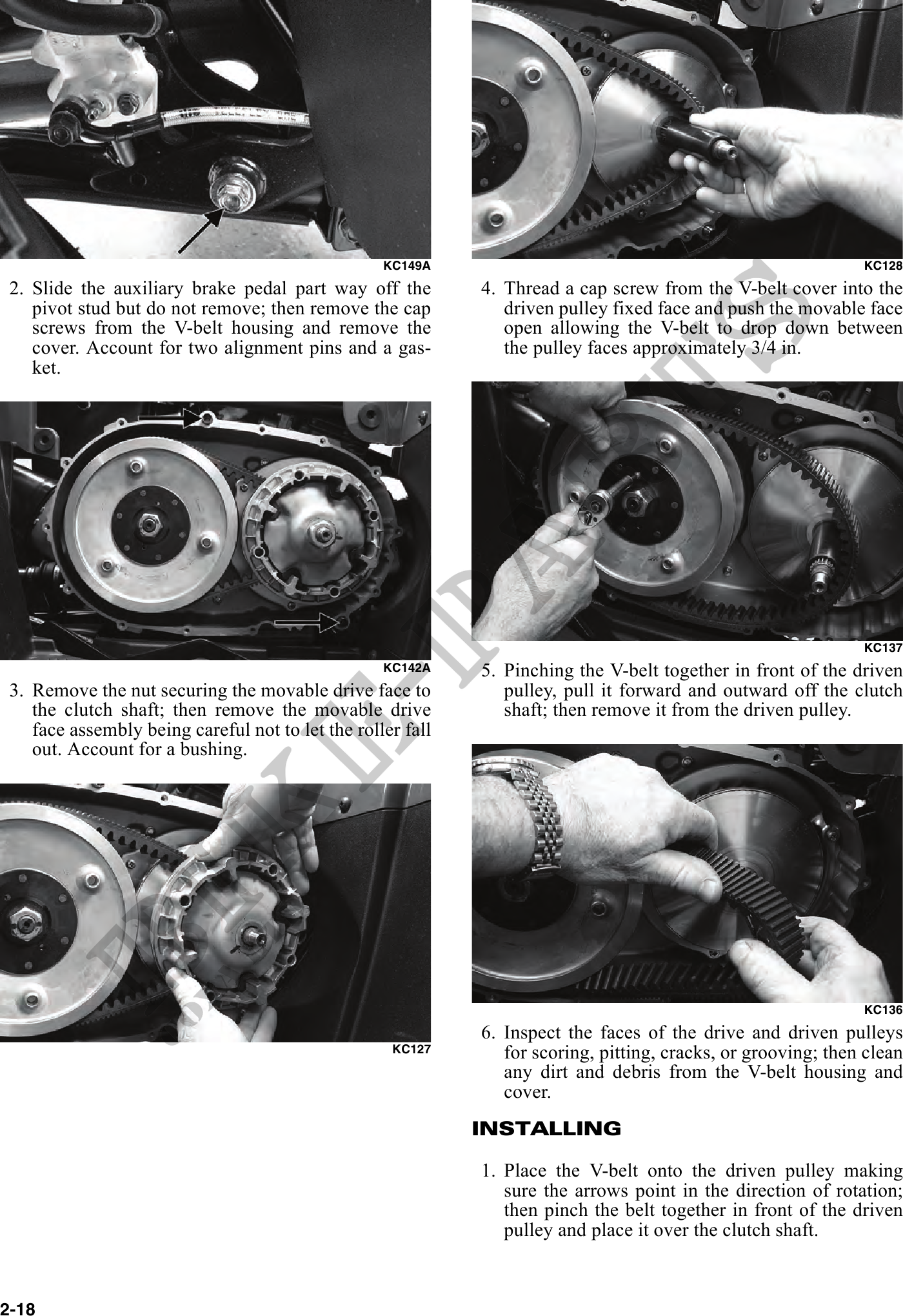
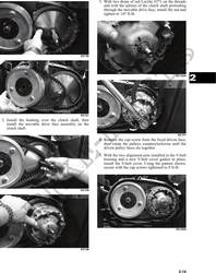
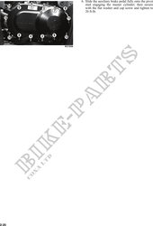
2. Slide the auxiliary brake pedal part way off the 4. Thread a cap screw from the V-belt cover into the
pivot stud but do not remove; then remove the cap driven pulley fixed face and push the movable face
screws from the V-belt housing and remove the open allowing the V-belt to drop down between
cover. Account for two alignment pins and a gas- the pulley faces approximately 3/4 in.
ket.
KC137
KC142A 5. Pinching the V-belt together in front of the driven
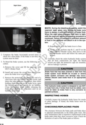
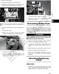
3. Remove the nut securing the movable drive face to pulley, pull it forward and outward off the clutch
the clutch shaft; then remove the movable drive shaft; then remove it from the driven pulley.
face assembly being careful not to let the roller fall
out. Account for a bushing.
KC136
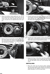
6. Inspect the faces of the drive and driven pulleys
KC127 for scoring, pitting, cracks, or grooving; then clean
any dirt and debris from the V-belt housing and
cover.
INSTALLING
1. Place the V-belt onto the driven pulley making
sure the arrows point in the direction of rotation;
then pinch the belt together in front of the driven
pulley and place it over the clutch shaft.
2-18