Choose your country
We work in partnership with many official Kymco dealers around the world.
You can select the country of your choice from the list below, whatever your choice, we can deliver worldwide!
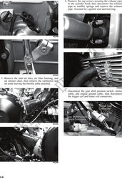
2. Remove the heat shield; then remove the gas tank
(see Section 4).
Table of Contents
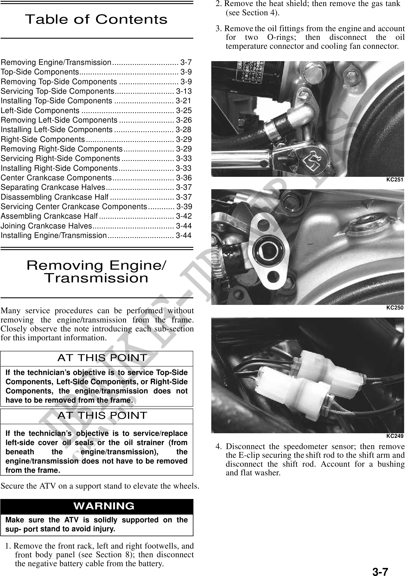
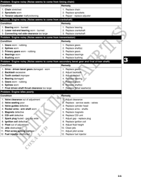
3. Remove the oil fittings from the engine and account
for two O-rings; then disconnect the oil
temperature connector and cooling fan connector.
Removing Engine/Transmission .............................. 3-7
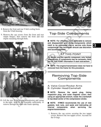
Top-Side Components............................................. 3-9
Removing Top-Side Components ........................... 3-9
Servicing Top-Side Components........................... 3-13
Installing Top-Side Components ........................... 3-21
Left-Side Components .......................................... 3-25
Removing Left-Side Components ......................... 3-26
Installing Left-Side Components ........................... 3-28
Right-Side Components ........................................ 3-29
Removing Right-Side Components ....................... 3-29
Servicing Right-Side Components ........................ 3-33
Installing Right-Side Components......................... 3-33
Center Crankcase Components............................ 3-36 KC251
Separating Crankcase Halves............................... 3-37
Disassembling Crankcase Half ............................. 3-37
Servicing Center Crankcase Components ............ 3-39
Assembling Crankcase Half .................................. 3-42 3
Joining Crankcase Halves..................................... 3-44
Installing Engine/Transmission .............................. 3-44
Removing Engine/
Transmission
KC250
Many service procedures can be performed without
removing the engine/transmission from the frame.
Closely observe the note introducing each sub-section
for this important information.
AT THIS POINT
If the technician's objective is to service Top-Side
Components, Left-Side Components, or Right-Side
Components, the engine/transmission does not
have to be removed from the frame.
AT THIS POINT
If the technician's objective is to service/replace KC249
left-side cover oil seals or the oil strainer (from
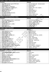
4. Disconnect the speedometer sensor; then remove
beneath the engine/transmission), the the E-clip securing the shift rod to the shift arm and
engine/transmission does not have to be removed disconnect the shift rod. Account for a bushing
from the frame. and flat washer.
Secure the ATV on a support stand to elevate the wheels.
WARNING
Make sure the ATV is solidly supported on the
sup- port stand to avoid injury.
1. Remove the front rack, left and right footwells, and
front body panel (see Section 8); then disconnect
the negative battery cable from the battery.
3-7