Choose your country
We work in partnership with many official Kymco dealers around the world.
You can select the country of your choice from the list below, whatever your choice, we can deliver worldwide!
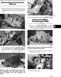
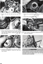
10. Remove the secondary drive gear/secondary NOTE: Continue to remove, measure, and install
driven gear retaining nut. From inside the crank- until backlash measurement is within tolerance.
case using a rubber mallet, drive out the output Note the following chart.
shaft assembly. Account for the output shaft, a
shim, a washer, and the nut.
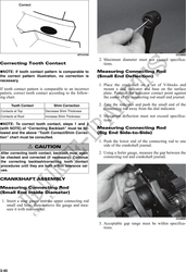
Backlash Measurement Shim Correction
AT THIS POINT Under 0.05 mm (0.002 in.) Decrease Shim
Thickness
To service crankshaft assembly, see Servicing Cen-
At 0.05-0.33 mm No Correction Required
ter Crankcase Components sub-section. (0.002-0.013 in.)
Over 0.33 mm (0.013 in.) Increase Shim
Thickness
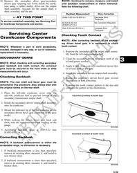
Servicing Center Checking Tooth Contact
Crankcase Components
NOTE: After correcting backlash of the second-
ary driven bevel gear, it is necessary to check
NOTE: Whenever a part is worn excessively, tooth contact.
cracked, damaged in any way, or out of tolerance,
replacement is necessary. 1. Remove the secondary driven output shaft assem-
bly from the left-side crankcase half.
SECONDARY GEARS
NOTE: When checking and correcting secondary
2. Clean the secondary driven bevel gear teeth of old
oil and grease residue. 3
gear backlash and tooth contact, the universal 3. Apply a thin, even coat of a machinist-layout dye
joint must be secured to the front shaft or false to several teeth of the gear.
measurements will occur.
4. Install the secondary driven output shaft assembly.
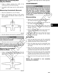
Checking Backlash 5. Rotate the secondary driven bevel gear several
revolutions in both directions.
NOTE: The rear shaft and bevel gear must be
removed for this procedure. Also, always start with 6. Examine the tooth contact pattern in the dye and
the original shims on the rear shaft. compare the pattern to the illustrations.
1. Place the left-side crankcase cover onto the
left-side crankcase half to prevent runout of the
secondary transmission output shaft.
2. Install the secondary driven output shaft assembly
onto the crankcase.
3. Mount the indicator tip of the dial indicator on the
secondary driven bevel gear (centered on the gear
tooth).
4. While rocking the driven bevel gear back and
forth, note the maximum backlash reading on the
gauge.
ATV-0103
5. Acceptable backlash range is 0.05-0.33 mm
(0.002-0.013 in.).
Correcting Backlash
NOTE: If backlash measurement is within the
acceptable range, no correction is necessary.
1. If backlash measurement is less than specified,
remove an existing shim, measure it, and install a
new thinner shim.
2. If backlash measurement is more than specified,
remove an existing shim, measure it, and install a ATV-0105
thicker shim.
3-39