Choose your country
We work in partnership with many official Kymco dealers around the world.
You can select the country of your choice from the list below, whatever your choice, we can deliver worldwide!
Electrical System RPM Limiter
NOTE: The ATV is equipped with a CDI that
This section has been organized into sub-sections
which show procedures for the complete servicing of retards ignition timing when maximum RPM is
the KYMCO ATV electrical system. approached. When the RPM limiter is activated, it
could be misinterpreted as a high-speed misfire.
NOTE: Some photographs and illustrations used
in this section are used for clarity purposes only
and are not designed to depict actual conditions.
Testing Electrical
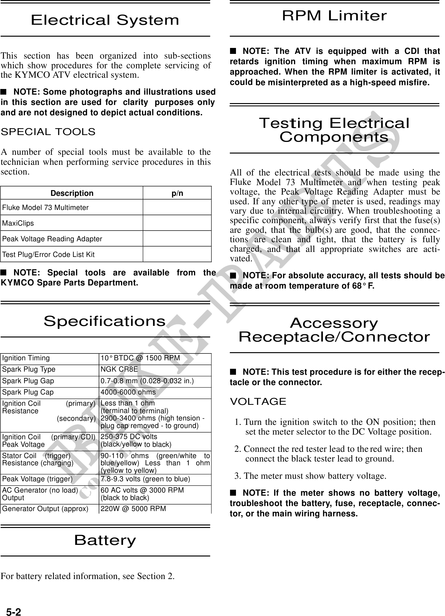
SPECIAL TOOLS
Components
A number of special tools must be available to the
technician when performing service procedures in this
section. All of the electrical tests should be made using the
Fluke Model 73 Multimeter and when testing peak
Description p/n voltage, the Peak Voltage Reading Adapter must be
used. If any other type of meter is used, readings may
Fluke Model 73 Multimeter
vary due to internal circuitry. When troubleshooting a
MaxiClips specific component, always verify first that the fuse(s)
are good, that the bulb(s) are good, that the connec-
Peak Voltage Reading Adapter tions are clean and tight, that the battery is fully
charged, and that all appropriate switches are acti-
Test Plug/Error Code List Kit
vated.
NOTE: Special tools are available from the NOTE: For absolute accuracy, all tests should be
KYMCO Spare Parts Department. made at room temperature of 68° F.
Specifications Accessory
Receptacle/Connector
Ignition Timing 10° BTDC @ 1500 RPM
Spark Plug Type NGK CR8E NOTE: This test procedure is for either the recep-
Spark Plug Gap 0.7-0.8 mm (0.028-0.032 in.) tacle or the connector.
Spark Plug Cap 4000-6000 ohms
Ignition Coil (primary) Less than 1 ohm VOLTAGE
Resistance (terminal to terminal)
(secondary) 2900-3400 ohms (high tension -
plug cap removed - to ground) 1. Turn the ignition switch to the ON position; then
set the meter selector to the DC Voltage position.
Ignition Coil (primary/CDI) 250-375 DC volts
Peak Voltage (black/yellow to black)
2. Connect the red tester lead to the red wire; then
Stator Coil (trigger) 90-110 ohms (green/white to connect the black tester lead to ground.
Resistance (charging) blue/yellow) Less than 1 ohm
(yellow to yellow)
Peak Voltage (trigger) 7.8-9.3 volts (green to blue) 3. The meter must show battery voltage.
AC Generator (no load) 60 AC volts @ 3000 RPM NOTE: If the meter shows no battery voltage,
Output (black to black)
troubleshoot the battery, fuse, receptacle, connec-
Generator Output (approx) 220W @ 5000 RPM
tor, or the main wiring harness.
Battery
For battery related information, see Section 2.
5-2