Choose your country
We work in partnership with many official Kymco dealers around the world.
You can select the country of your choice from the list below, whatever your choice, we can deliver worldwide!
8. Apply thread tape to the threads of the switch; then NOTE: If the meter shows more than 1 ohm of
install the switch and tighten securely. resistance, troubleshoot or replace the
switch/component, the connector, or the switch
9. Connect the switch leads. wiring harness.
NOTE: To determine if the fan motor is good,
Fan Motor connect the blue wire from the fan connector to
the positive side of a 12 volt DC power supply;
then connect the black wire from the fan connector
to the negative side. The fan should operate.
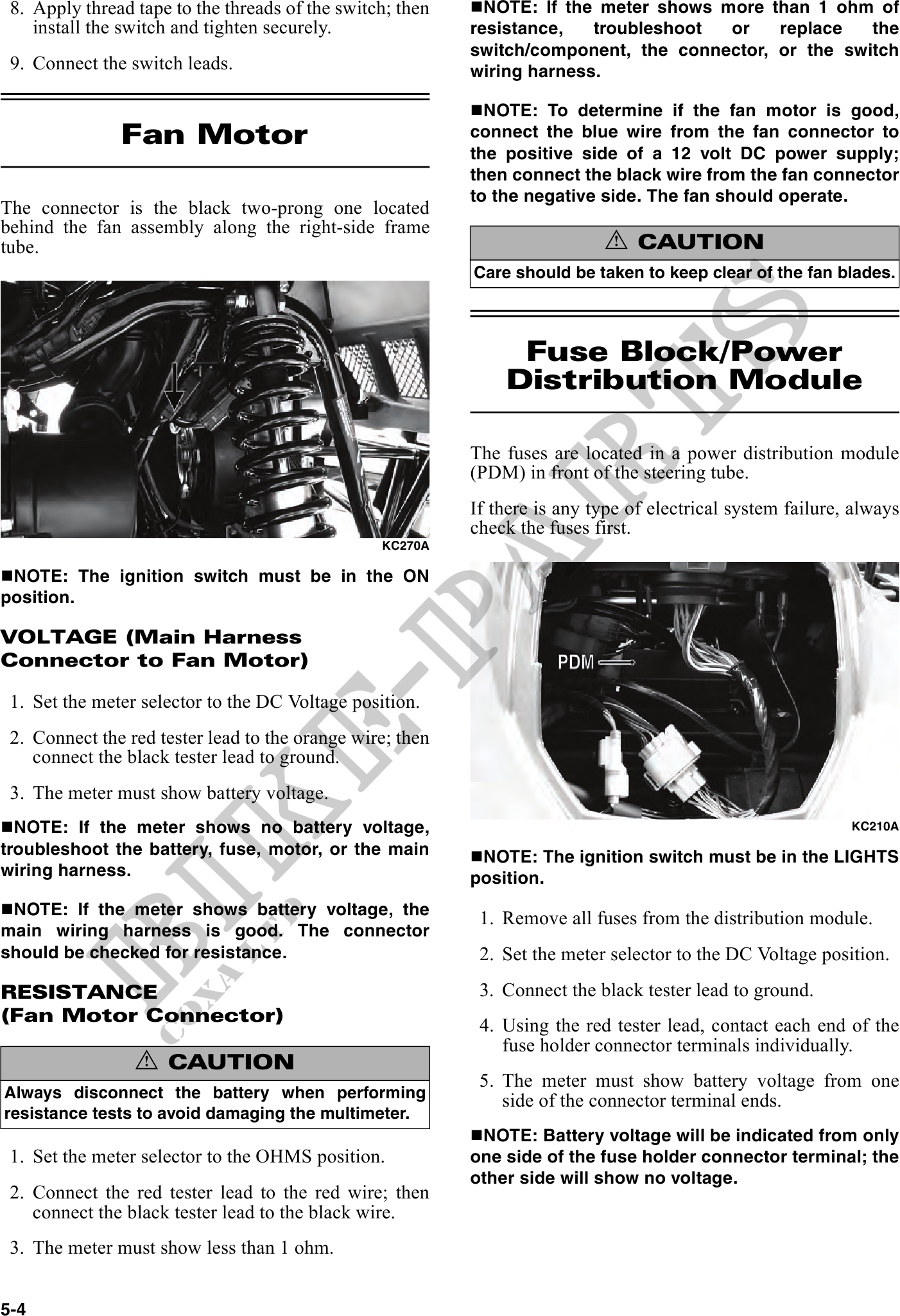
The connector is the black two-prong one located
behind the fan assembly along the right-side frame
tube. ! CAUTION
Care should be taken to keep clear of the fan blades.
Fuse Block/Power
Distribution Module
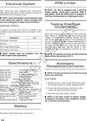
The fuses are located in a power distribution module
(PDM) in front of the steering tube.
If there is any type of electrical system failure, always
check the fuses first.
KC270A
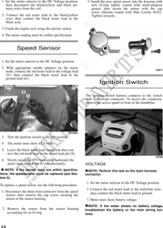
NOTE: The ignition switch must be in the ON
position.
VOLTAGE (Main Harness
Connector to Fan Motor)
1. Set the meter selector to the DC Voltage position.
2. Connect the red tester lead to the orange wire; then
connect the black tester lead to ground.
3. The meter must show battery voltage.
NOTE: If the meter shows no battery voltage, KC210A
troubleshoot the battery, fuse, motor, or the main NOTE: The ignition switch must be in the LIGHTS
wiring harness. position.
NOTE: If the meter shows battery voltage, the
1. Remove all fuses from the distribution module.
main wiring harness is good. The connector
should be checked for resistance. 2. Set the meter selector to the DC Voltage position.
RESISTANCE 3. Connect the black tester lead to ground.
(Fan Motor Connector) 4. Using the red tester lead, contact each end of the
fuse holder connector terminals individually.
! CAUTION
5. The meter must show battery voltage from one
Always disconnect the battery when performing side of the connector terminal ends.
resistance tests to avoid damaging the multimeter.
NOTE: Battery voltage will be indicated from only
1. Set the meter selector to the OHMS position. one side of the fuse holder connector terminal; the
other side will show no voltage.
2. Connect the red tester lead to the red wire; then
connect the black tester lead to the black wire.
3. The meter must show less than 1 ohm.
5-4