quannon 125 Workshop-manual : Page 57

Microfiches
Image preview

Page 55

Image preview

Page 56

Image preview

Page 58

Image preview

Page 59

1 5 10 15 20 25 30 35 40 45 50 55 60 65 70 75 80 85 90 95 100 105 110 115 120 125 130 135 140 145 150 155 159
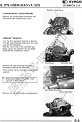
          6. CYLINDER HEAD/VALVES                                                       QUANNON 125

 SERVICE INFORMATION
 GENERAL INSTRUCTIONS
 · The cylinder head can be serviced with the engine installed in the frame.
 · When assembling, apply molybdenum disulfide grease or engine oil to the valve guide movable
   parts and valve arm sliding surfaces for initial lubrication.
 · The valve rocker arms are lubricated by engine oil through the cylinder head engine oil passages.
   Clean and unclog the oil passages before assembling the cylinder head.
 · After disassembly, clean the removed parts and dry them with compressed air before inspection.
 · After removal, mark and arrange the removed parts in order. When assembling, install them in
   the reverse order of removal.

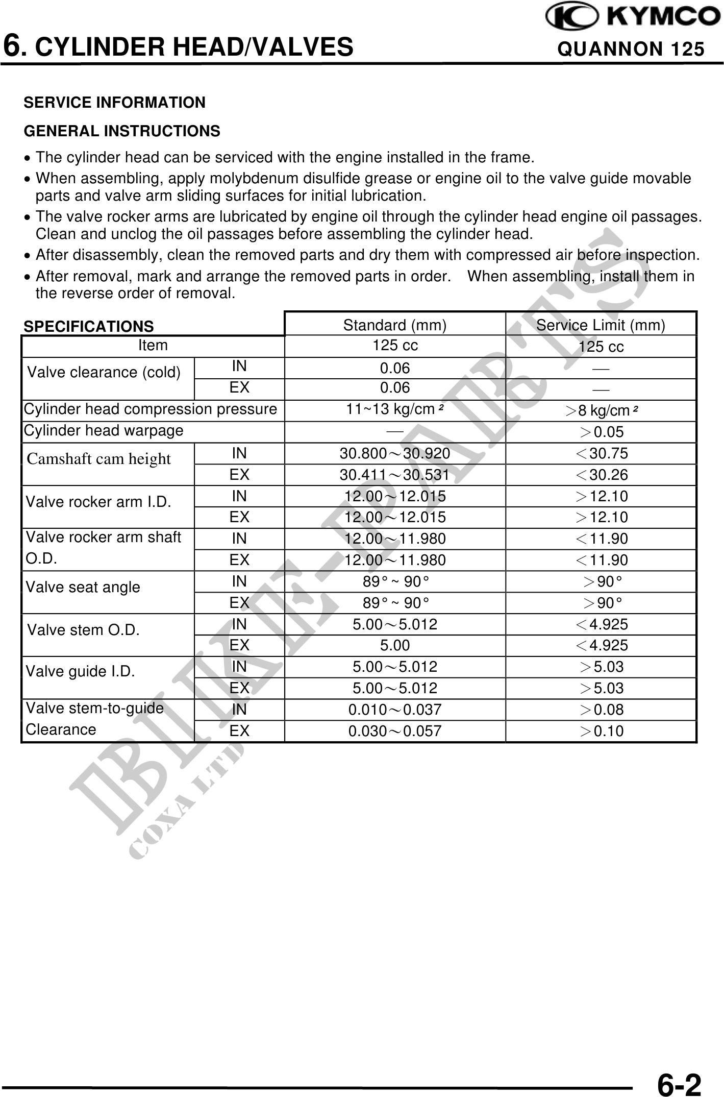
 SPECIFICATIONS                                Standard (mm)               Service Limit (mm)
             Item                                    125 cc                      125 cc
 Valve clearance (cold)      IN                       0.06                         
                             EX                       0.06                         
 Cylinder head compression pressure             11~13 kg/cm                   8 kg/cm
 Cylinder head warpage                                                           0.05
 Camshaft cam height         IN                30.80030.920                     30.75
                             EX                30.41130.531                     30.26
 Valve rocker arm I.D.       IN                 12.0012.015                     12.10
                             EX                 12.0012.015                     12.10
 Valve rocker arm shaft      IN                 12.0011.980                     11.90
 O.D.                        EX                 12.0011.980                     11.90
 Valve seat angle            IN                    89° ~ 90°                     90°
                             EX                    89° ~ 90°                     90°
 Valve stem O.D.             IN                   5.005.012                     4.925
                             EX                       5.00                      4.925
 Valve guide I.D.            IN                   5.005.012                      5.03
                             EX                   5.005.012                      5.03
 Valve stem-to-guide         IN                  0.0100.037                      0.08
 Clearance                   EX                  0.0300.057                      0.10


                                                                                             6-2